7 p250 Laser Quick Start Guide Version 3.1
p250 Quick Start Guide
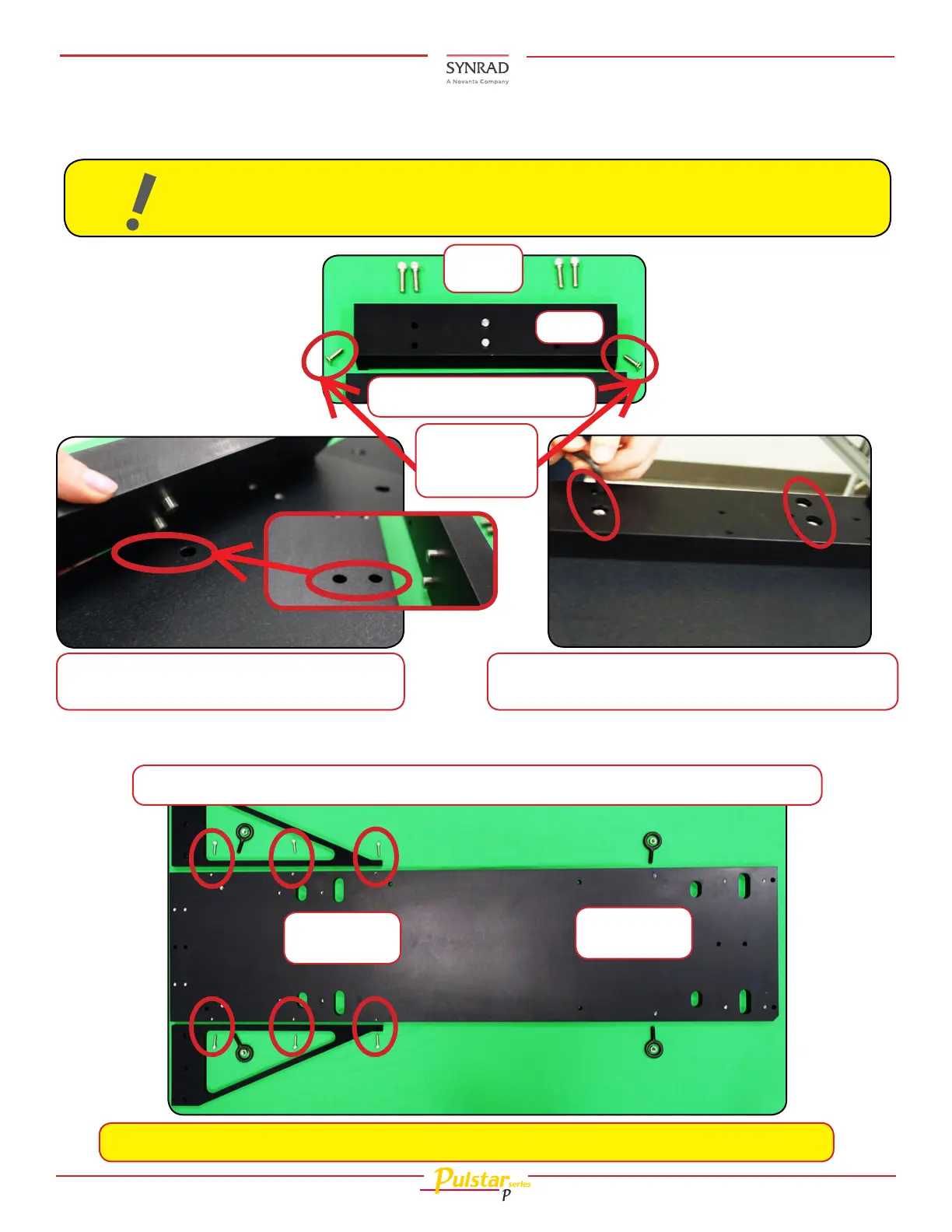
9.2 Place the bar on the rail aligning the
pegs as shown.
9.3 Attach the bar securely to the rail with the four
(4) bar hardware screws shown in 7.1.
9. Place the bar onto the rail as shown below.
Bar
(4) Bar
screws
9.1 Bar and hardware.
10.
Install the triangle bars as shown below.
Note: The Laser feet screws are shown in their nal locations for clarity on the rail above.
10.1 The Triangle bar screws and nal placement on the rail are shown circled in red below.
Laser feet
screws
Two (2) Bar/
Triangle bar end
screws
When attaching the Marking Head to the Laser, make sure the notch is as shown in gure
below before going on to the next step.
Note:
Laser feet
screws
Mounting (Continued):