2 Configuration Units
2 - 6
NA-series Programmable Terminal Hardware User’s Manual (V117)
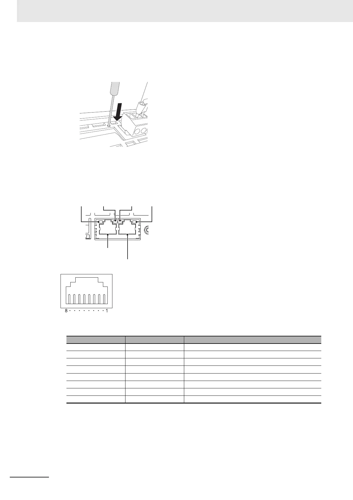
Reset Switch
Use a precision screwdriver or similar device with a diameter of less than 2.4 mm. The reset switch
performs the same function as cycling the power supply.
Ethernet Ports
• Port Pin Arrangement and Indicator Locations
• Connecting Devices That Support IEEE 802.3i (10BASE-T) or IEEE 802.3u (100BASE-TX)
Pin No. Signal name Name
1 TD+ Twisted-pair output (differential output)
2 TD- Twisted-pair output (differential output)
3 RD+ Twisted-pair input (differential input)
4 BI D+ Protection circuit
5 BI D- Protection circuit
6 RD- Twisted-pair input (differential input)
7 BI D+ Protection circuit
8 BI D- Protection circuit
Ethernet port 1
Ethernet port 2
Ethernet Port 1
Indicators
Ethernet Port 2
Indicators
ACT
indicator
LINK
indicator
ACT
indicator
LINK
indicator