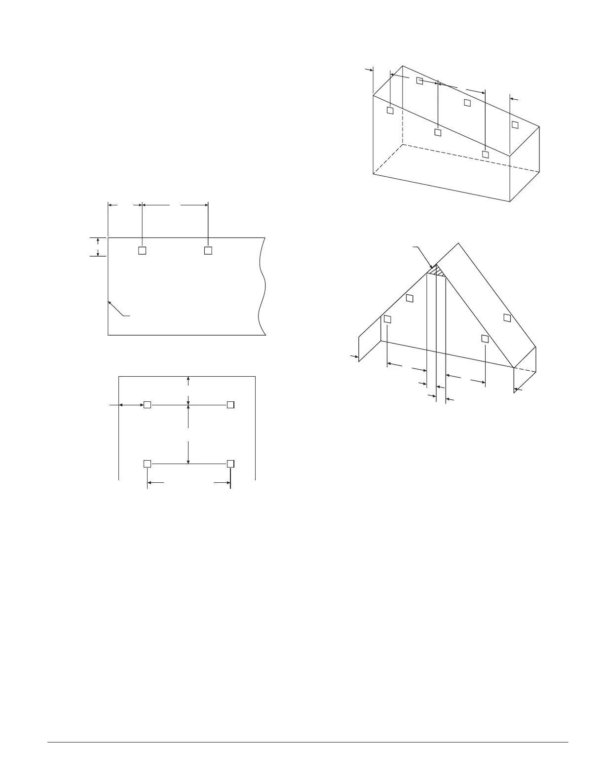
In a room with a smooth ceiling, detectors should be spaced
between 30 and 60 feet. One-half that spacing between the
beam and the sidewall may be used as a guide. See Figure
1. The beam detector can be mounted with the receiver
on one wall and the transmitter on the opposite wall, or
both suspended from the ceiling, or any wall/ceiling com-
bination. In the case of the ceiling mount, the distance
from the end walls should not exceed one-quarter of the
selected spacing (7.5 ft. maximum if the spacing is 30 ft.).
See Figure 2.
Figure 1. Spacing for smooth ceiling (side view):
C0536-00
Figure 2. Spacing for smooth ceiling (top view):
30 FEET MINIMUM
330 FEET MAXIMUM
TX RX
S
TX RX
1/2 S MAXIMUM
1/4 S
MAX.
C0537-00
In the case of peaked or sloped ceilings, codes may specify
spacing of detectors by using horizontal spacing from the
peak of the roof or ceiling. Figures 3 and 4 show the spac-
ing for both the shed type and peaked type sloped ceilings
On smooth ceilings, beam smoke detectors should gener-
ally be mounted between 12 and 18 inches from the ceiling.
In many cases, however, the location and sensitivity of the
detectors shall be the result of an engineering evaluation
that includes the following: structural features, size and
shape of the room and bays, occupancy and uses of the
area, ceiling height, ceiling shape, surface and obstructions,
ventilation, ambient environment, burning characteristics
of the combustible materials present, and the configuration
of the contents in the area to be protected.
Figure 3. Sloped ceiling (shed type):
S
3 FT. MAX.
S
1/2 S MAX.
Tx
Rx
C0538-00
Figure 4. Sloped ceiling (peaked type):
1/2 S S
S
1/2 S
3 FT.
MAX.
3 FT.
MAX.
MOUNT DETECTOR
ANYWHERE IN THIS AREA
Tx
Rx
C0539-00
Mounting Locations
Beam detectors require a stable mounting surface for
proper operation. A surface which moves, shifts, vibrates,
or warps over time will cause false alarm or trouble condi-
tions. Initial selection of a proper mounting surface will
eliminate false alarms and nuisance trouble signals.
Mount the detector on a stable mounting surface, such as
brick, concrete, a sturdy load-bearing wall, support col-
umn, structural beam, or other surface that is not expected
to experience vibration or movement over time. DO NOT
MOUNT the beam detector on corrugated metal walls,
sheet metal walls, external building sheathing, external
siding, suspended ceilings, steel web trusses, rafters, non-
structural beam, joists, or other such surfaces.
D400-18-00 3 I56-494-13R
PRINTED IN MEXICO