I56-2081-013 © System Sensor 2009DB200-01-01
2
OPTICAL LINE OF SIGHT
WALL
MOUNTING
SCREW X 4
COVER
SCREW
X 4
W
ALL
ACCEPTABLE MOUNTING
LOCATIONS FOR REFLECTOR
REFLECTOR
REFLECTOR
Figure 2a: Reflector Mounting Guidelines
Figure 2b: Reflector Mounting Guidelines
Please refer to the relevant kit instructions if the transmitter/receiver is
to be mounted onto the 6500-SMK/BEAMSMK or 6500-MMK/
BEAMMMK allowing more flexibility for cable entry.
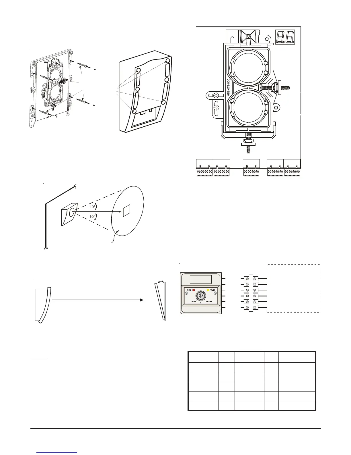
Figure 1: Transmitter/Receiver Wall Mounting
The reflector is mounted directly to the wall using all four of its
mounting holes, one in each corner. The reflector must be mounted
such that the plane of the reflector is perpendicular to the optical line of
sight to the transmitter/receiver unit. The maximum tolerance for non-
perpendicular mounting locations is 10°. If this tolerance is not
possible, then the MMK should be used, see MMK instructions for
mounting details.
10° MAXIMUM
Figure 3: Detector Terminal Connections
FAULT N.C.
FAULT COM
REMOTE TROUBLE OUT
NOT USED
REMOTE ALARM OUT
AUX (-)
TEST INPUT
RESET INPUT
POWER IN (+)
POWER IN (-)
POWER OUT (+)
POWER OUT (-)
ALARM N.O.
ALARM COM
ALARM N.O.
ALARM COM
ALARM LIMITING RESISTOR
ALARM LIMITING RESISTOR
SCHOTTKY DIODE (A)
SCHOTTKY DIODE (K)
Figure 4: 6500RTS-KEY Wiring
SEE 6500RTS-KEY INSTALLATION INSTRUCTIONS
FOR 6500RTS-KEY ELECTRICAL RATINGS
T2-1: REMOTE ALARM OUTPUT
T3-3: REMOTE TROUBLE OUTPUT
T2-2: AUX (-)
T2-4: RESET INPUT
T2-2: AUX (-)
T2-3: TEST INPUT
GREEN
ORANGE
BLACK
RED
YELLOW
YELLOW
WIRING
Note: All wiring must be installed in accordance with local
requirements.
Warning: Before working on the system, notify the proper authorities
that the system is undergoing maintenance and will be temporarily out
of service.
Wiring connections are made to pluggable terminal blocks, which can
accept wire sizes from 1mm² to 2.5mm². For best results screened
cable should be used. Refer to the control panel instructions for cable
type limitations
6500R / 6500RS
1 2 3 4 1 2 3 4
1 2 3 4 1 2 3 4 1 2 3 4
T3 T2 T1 T4 T5
Signal Name Terminal Normal State Active Comment
State
Reset Input T2-4 High impedance 0V Momentarily connect to
Aux- to operate
Test Input T2-3 High impedance 0V Momentarily connect to
Aux- to operate
Aux- T2-2 0V - Internally connected to
Power -ve
Remote Alarm Out T2-1 High impedance +24V Via 2.2k ohms current
limit resistor
Remote Fault Out T3-3 High impedance +24V Via 2.2k ohms current
limit resistor
Table 0: Use of Input – Output Signals
.