I56-2081-013 © System Sensor 2009DB200-01-01
4
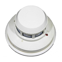
Figure 8: Coarse Alignment Procedure
REFLECTOR
SCREW
LOCATIONS
Note that the alignment gun site does not give an accurate alignment.
It is sufficient only as a starting point for the next step. On completion
of the fine adjustment procedure, the alignment gun site may not
appear to be centred on the reflector.
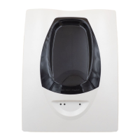
SCREW
LOCATIONS
Figure 9: Housing Screw Locations
EYE
Step 2. Fine Adjustment
See figures 6 to 8.
1. Ensure that no objects are in the line of sight between the detector
and the reflector.
2. Depress the Alignment switch once. Both the digital display and
the yellow LED should turn on indicating that alignment mode has
been entered. The display should begin reading “- -” signifying an
electronic gain adjustment. After a few moments the display will
indicate a numeric value near 20.
Note: If the display reads “Lo” then the detector is not receiving
enough light from the reflector. Go back and repeat the course
alignment step and verify that the proper number of reflectors is
used for the installed distance. The display will continue to read
“Lo” until the detector receives enough light from the reflector to
continue with the fine adjustment step.
Note: In alignment mode (indicated by the yellow LED and the
numeric display) the sensitivity select and test switches are
disabled.
3. Once the display shows a number, begin adjusting the horizontal
and vertical alignment knobs one at a time to increase signal level
on the display. Continue adjusting each axis one at a time going
back and forth between them until a peak value is indicated. If a
value of 90 is achieved, the detector will reduce its electronic gain.
This will be indicated by a “- -” reading on the display. When this
happens halt any further adjustment until the display again reads a
numeric value. This process may occur more than once during
the fine adjustment step.
4. Once satisfied that it is not possible to achieve a higher reading on
the display depress the alignment switch to complete the fine
adjustment step. The digital display readout will turn “OFF” and the
yellow LED will remain “ON”.
Note: It may not be possible to achieve a figure close to 90 on the
display during the last adjustment iteration. Each time the figure 90
is reached the gain is reduced, making it more difficult to achieve
high values. Any number is acceptable, provided it is the highest
figure that can be achieved after the final gain adjustment.
At this time it is sensible to set the sensitivity of the detector using the
sensitivity switch and digital display. See SENSITIVITY SELECTION
for further details.
Step 3. Final Gain Adjustment
See figure 9.
In this step, the detector electronically adjusts its internal gain one final
time. It is necessary to complete this step with the outer housing
installed since the housing will change the amount of light received
from the reflector.
1. Install the outer housing of the detector. The housing is installed by
tightening the four captive screws, one in each corner of the
housing.
Note: The housing contains a gasket seal that protects the
detector circuitry from corrosion and moisture. To ensure that this
gasket performs correctly, it is necessary to tighten all four of the
screws holding the outer housing in place evenly.
2. Remove the protective film from the front surface of the outer
housing. Note that the outer housing may require cleaning if any
residue remains. Use only a soft, damp cloth; do not use any
solvents.
3. To initiate the final electronic gain adjustment, the reset switch
must be depressed using a small screwdriver or similar tool. Once
depressed the yellow LED will begin to blink. On completion, the
yellow LED will stop blinking and the green LED will begin blinking,
indicating that the gain adjustment was successful.
Note: Use caution not to block the line of sight between the
detector and reflector in this step.
4. Install the outer aesthetic ring by snapping it onto the outer
housing.
Note: If the outer aesthetic ring has been painted ensure that the
paint is completely dry before proceeding with this step.
Step 4. Final Verification
This step is required to insure the detector has been setup correctly
and will detect smoke at the proper sensitivity level.
1. With the detector functioning (dependant on the operation of the
control panel, this may be indicated by the green LED blinking),
completely block the reflector with a non-reflective opaque
material, for example this manual. After about 30 seconds, the
detector should enter either the fault or alarm condition. If the
detector does not enter the fault or alarm condition, there is a
problem with the installation.
2. Complete a sensitivity test of the detector as described in
SENSITIVITY TESTING below.
SENSITIVITY SELECTION
The sensitivity of the detector can be set only when the housing is
removed and the detector is not in the fine adjustment step of the
alignment mode. To enter the selection mode, press the sensitivity
button once (see figure 6). The digital display will illuminate and read
the current sensitivity setting in percent obscuration. Press the
sensitivity button again to rotate to the next setting. Once the required
setting is achieved (See table 1), the detector will exit the sensitivity
selection mode if no further switch presses occur.
RESET SWITCH
Sensitivity Setting % Obscuration Display Reading
Level 1 25 25
Level 2 30 30
Level 3 40 40
Level 4 50 50
Acclimate Level 1 30 to 50 A1
Acclimate Level 2 40 to 50 A2
Table 1: Sensitivity Settings
 Loading...