I56-2081-013 © System Sensor 2009DB200-01-01
3
DEUTSCH
ESPAÑOL
ENGLISH ITALIANO
FRANÇAIS
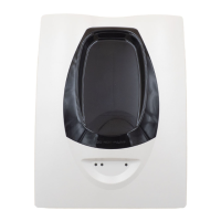
Figure 5: Wiring
Diagram
V OUT (+)
V OUT (-)
ALARM COM
V IN (+)
VIN (-)
ALARM COM
ALARM NO
ALARM NO
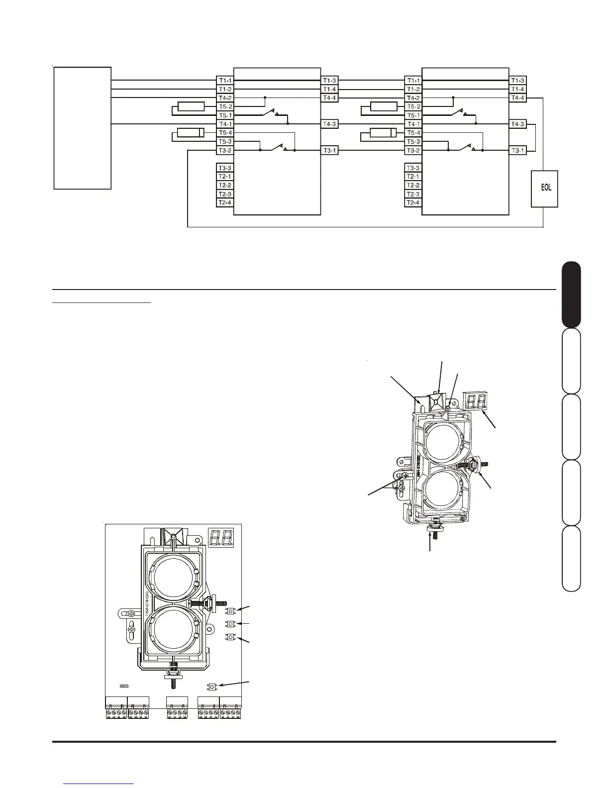
Figure 7: Alignment Adjustment Locations
ALIGNMENT PROCEDURE
Warning: When power is initially applied to the detector, before the
alignment procedure has been completed, it may enter fault or alarm.
To prevent unwanted alarms, disable the zone prior to applying power.
The alignment of the 6500R is divided into four steps: Coarse
alignment, fine adjustment, final gain adjustment, and final verification.
It is necessary for all four steps to be executed properly to ensure
proper alignment of the product.
Pre-Alignment Checklist
• Ensure that both the detector and reflector are mounted securely
to stable surfaces.
• Ensure that all wiring is correct, and that terminal blocks are fully
seated into their receptacles on the detector.
• Complete any wiring dressing to minimize movement to the
detector once the alignment procedure is completed.
• Ensure that the appropriate reflectors are used for the installed
distance.
• Ensure that the line of sight between the detector and reflector is
clear and that reflective objects are a minimum of 380mm from the
line of sight.
• Ensure that both the detector and reflector are mounted within their
operational parameters for off axis angles.
RESET
Terminals T5-1 and T5-2 provide connections used to complete the alarm circuit. A 0 ohm shunt, or current limiting resistor should be fitted
depending on the application; these are supplied separately. Refer to the panel manufacturer for correct current limiting resistor values.
Terminals T5-3 and T5-4 are used to connect the optional Schottky diode when used with active end of line monitoring; refer to panel
manufacturer for details. Do not fit the diode unless it is specifically required otherwise the functioning of the system will be affected. Diode
polarity must be observed for correct operation.
EXTERNAL ALARM
LIMITING RESISTOR
OR SHUNT
POWER (+)
POWER (-)
INITIATING ZONE (+)
INITIATING ZONE (-)
• Disable the zone or system to prevent unwanted alarms before
applying power.
• Ensure power to the detector is “ON”.
FAULT COM
REMOTE FAULT OUTPUT
REMOTE ALARM OUTPUT
AUX (-)
TEST INPUT
RESET INPUT
Figure 6: Switch Locations
ALIGNMENT
POSITION
INDICATOR
OPTICS LOCK-DOWN
SCREWS X 2
CONTROL PANEL
ALIGNMENT
SENSITIVITY
TEST
OPTIONAL
SCHOTTKY DIODE
ALIGNMENT
MIRROR
FAULT NC FAULT NC
FAULT COM
REMOTE FAULT OUTPUT
REMOTE ALARM OUTPUT
AUX (-)
TEST INPUT
RESET INPUT
V IN (+)
VIN (-)
ALARM COM
ALARM NO
ZONE
EOL
DEVICE
V OUT (+)
V OUT (-)
ALARM COM
ALARM NO
Step 1. Coarse Alignment
See figures 6 and 7.
1. Ensure that both of the optics lock-down screws are loosened so
that the optics will move freely.
2. Looking through the alignment mirror at both the alignment gun
sight and reflector simultaneously, locate the position of the
reflector in the optical sight. Note that initially this step will require
some practice. An orange sticky label is supplied, which may be
temporarily mounted next to the reflector to aid initial location if the
distance between the reflector and the detector is large.
3. Once the reflector has been located, begin to adjust both the
horizontal and vertical alignment knobs so that the reflector
becomes centred in the alignment mirror. Caution: If the optics are
incorrectly aligned in this step, it will not be possible to proceed
with the next step.
HORIZONTAL
ADJUSTMENT
ALIGNMENT
GUN SIGHT
VERTICAL
ADJUSTMENT
DIGITAL SIGNAL
STRENGTH
READOUT
6500R/6500RS
6500R/6500RS
AK
AK