I56-2081-013 © System Sensor 2009DB200-01-01
5
DEUTSCH
ESPAÑOL
ENGLISH ITALIANO
FRANÇAIS
Test Failure Checks
If the detector fails either the sensitivity or functional test, several
steps should be taken before returning the unit to determine if it is
faulty, or simply needs to be re-adjusted. These steps include:
1. Verify all wiring connections and appropriate power is applied to the
detector.
2. Verify that the optical line of sight is free from obstructions and
reflective objects.
It is imperative that at least 90% of the received light is from the
reflector alone, otherwise sensitivity cannot be assured.
3. Apply the maintenance procedure in this manual. Repeat the test
procedure. If the detector still fails the test procedure proceed with
step 4.
4. Repeat the alignment procedure in this manual. If the alignment
procedure is successful repeat the test procedure. If the detector
still fails the test it should be returned for repair.
6500 BEAM DETECTOR: SET-UP PROCEDURE SUMMARY
Beam Alignment – ensure power is on
Course Alignment
Carry out using target eyepiece
Adjust using horizontal and vertical thumb screws
Fine Adjustment
Initiate using
Alignment Switch
Continue adjustment using horizontal and vertical thumb screws
When the adjustment is complete press the
Alignment Switch
Sensitivity Setting
Select using
Sensitivity Switch
Final Gain Adjustment – ensure front cover is fitted
Initiate using the
Reset Switch
Completed when the green LED blinks
Final Verification
Use obscuration filters or reflector test card to initiate
Fire
and
Fault
signals
MAINTENANCE
Note: Before cleaning the detector, notify the proper authorities that
the smoke detector system is undergoing maintenance, and therefore
the system will be temporarily out of service. Disable the zone or
system undergoing maintenance to prevent unwanted alarms.
1. Carefully clean the outer housing lens face. A damp soft cloth with
a mild soap may be used. Avoid products with solvents or
ammonia.
2. Carefully clean the reflector. A damp soft cloth with a mild soap
may be used. Avoid products with solvents or ammonia.
Functional Testing
For periodic maintenance functional testing, the detector can either be
tested using the Calibrated Test Filter method, by using the local test
switch on the transmitter receiver unit or remotely using the Remote
Test Station.
The Remote Test Station, 6500RTS-KEY, can be used with the 6500R
beam smoke detector. Follow the Installation and Maintenance
instructions included with the 6500RTS-KEY for proper use.
The 6500RS is equipped with an integral sensitivity test feature that
consists of a calibrated test filter attached to a servomotor inside the
detector optics. When a test is initiated using the remote test station or
local test switch the test filter is moved in the pathway of the light
beam. If the correct level of signal reduction is received the detector
will enter alarm. If the proper level of signal reduction was not
achieved, indicating that the sensitivity of the detector is out of
tolerance, the detector will enter the fault condition.
Note: This test should satisfy most local periodic maintenance and
testing requirements.
If the detector fails this test, refer to the Test Failure Checks described
above.
PAINTING
The outer aesthetic ring may be painted using enamel or acrylic paints
either by brush or spray.
Note: Never paint the flat lens surface of the outer housing.
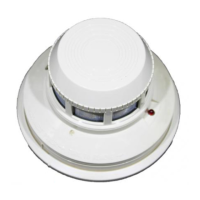
In addition to the four standard sensitivity selections the detector has
two Acclimate settings. When either of these settings is chosen the
detector will automatically adjust its sensitivity using advanced
software algorithms to select the optimum sensitivity for the
environment. The sensitivity will be continuously adjusted within the
ranges specified in graph 1.
Total obscuration can be converted to percent per metre assuming
uniform smoke density for the entire length of the beam. Graph 1
converts total obscuration to percent per metre for all acceptable
sensitivity settings.
SENSITIVITY TESTING
NOTES:
1. Before testing, notify the proper authorities that the smoke detector
system is undergoing maintenance, and therefore the system will
be temporarily out of service. Disable the zone or system
undergoing maintenance to prevent unwanted alarms.
2. Before testing the detector, check for the presence of the flashing
green LED at the receiver, making sure not to disturb or block the
beam. If it does not flash and the detector is not in fault or alarm,
power has been lost to the detector.
Detectors must be tested after installation and following periodic
maintenance. The sensitivity of the 6500R may be tested as follows:
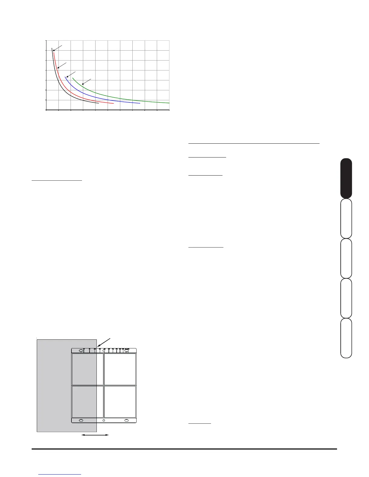
Calibrated Test Filter Method
The sensitivity of the detector can be tested using an opaque material
( such as this manual ) to cover the reflector by an amount indicated
by the graduated scale on the reflector, see Figure 10.
1. Verify the sensitivity setting of the detector in % obscuration. See
the Sensitivity Selection section of this manual for sensitivity
determination if sensitivity is unknown.
2. Place the blocking material over the reflector, lining it up with the
graduated marks that are 10 less than the detector setting in %
obscuration. The detector should not alarm or fault. Keep the
material in place for a minimum of 1 minute.
3. Place the blocking material over the reflector lining it up with the
graduated marks that are 10 more than the detector setting in %
obscuration. The detector should enter alarm within 1 minute.
4. The detector can be reset with the reset switch on the detector
unit or remote reset.
Figure 10. Reflector Test Card Procedure
LINE UP EDGE OF BLOCKING MATERIAL
WITH APPROPRIATE OBSCURATION LEVEL
MOVE BLOCKING MATERIAL TO
DESIRED AMOUNT OF OBSCURATION
GRAPH 1: SENSITIVITY (%M vs DISTANCE)
(Assuming Uniform Smoke Distribution)
0
1
2
3
4
5
6
7
0 102030405060708090100
Distance (Metres)
Obscuration (%/Metre)
Level 1
Level 2
Level 3
Level 4
 Loading...