D100-99-00 2 I56-2170-04R
After power-up has completed and the detector is functioning
normally within its listed sensitivity range, the green LED blinks
once every five seconds. If the detector is in need of maintenance
because its sensitivity has shifted outside the listed limits, the red
LED blinks once every five seconds. When the detector is in the
alarm mode, the red LED latches on. The LED indication must not
be used in lieu of the tests specified under Testing. In a freeze
trouble condition, the red LED will blink once every 10 seconds
(refer to Table 1).
To measure the detector’s sensitivity, the i
3
Series Model SENS-
RDR Infrared Sensitivity Reader tool (see Figure 4) should be used.
Refer to instructions manual D100-98-00 for the proper use of the
SENS-RDR.
Models 2WTR-B and 2WTA-B also include an output that allows an
optional Model RA400Z Remote Annunciator to be connected.
Mounting
General spacing guidelines are 30′× 30′, with each detector cover-
ing 900 ft
2
under maximum conditions.
Consult NFPA 72, the local Authority Having Jurisdiction (AHJ),
and/or applicable codes for specific information regarding the
spacing and placement of smoke detectors.
Each i
3
Series detector is supplied with a mounting base that can
be ceiling- or wall-mounted:
1. To a single gang box, or
2. To a 3
1
⁄2-inch or 4-inch octagonal box, or
3. To a 4-inch square box with a plaster ring, or
4. Direct mount or to ceiling using drywall fasteners.
Figure 1: Mounting of Detector
The i
3
Series heads and bases are keyed so that all heads will only fit
into their respective bases. One model 4-wire relay base will accept
the 4WTR-B, 4WTAR-B and 4WITAR-B detector heads and no others.
The 2WTR-B, 2WTA-B and 4WTA-B will only fit into their respective
mounting bases and no others. The heads and bases are clearly iden-
tified as either 2-wire or 4-wire. When mounting the i
3
Series, ensure
that the head is mounted to the correct base, and the test switch is
aligned with the tamper release tab.
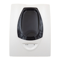
Tamper-Resistant Feature
The i
3
Series detectors include a tamper-resistant feature that pre-
vents removal from the mounting base without the use of a tool.
To engage the tamper-resistant feature, cut the small plastic tab
located on the mounting base (Figure 2), and then install the detec-
tor. To remove the detector from the base once it has been made
tamper resistant, use a small screwdriver to depress the square
tamper release tab, located on the skirt of the mounting base, and
turn the detector counterclockwise.
Installation Guidelines
The i
3
Series detectors represent an advancement over the previous
sounder and Form C relay models and are designed to be used with the
2W-MOD2 and RRS-MOD only. Do not mix detector models on a zone.
Figure 2: Tamper-Resistant Feature
SNAP OFF TAB
FOR TAMPER LOCK
TAMPER
RELEASE TAB
DIRECT MOUNT
HOLES
Wiring Installation Guidelines
All wiring must be installed in compliance with the NFPA 70,
National Electrical Code, applicable state and local codes, and any
special requirements of the local Authority Having Jurisdiction.
Proper wire gauges should be used. The conductors used to con-
nect smoke detectors to the alarm control panel and accessory
devices should be color-coded to reduce the likelihood of wiring
errors. Improper connections can prevent a system from respond-
ing properly in the event of a fire.
The screw terminals in the mounting base will accept 14–22
gauge wire. For best system performance, all wiring should be
installed in separate grounded conduit; do not mix fire alarm
system wiring in the same conduit as any other electrical wiring.
Twisted pair may be used to provide additional protection against
extraneous electrical interference.
Wire connections are made by stripping approximately
1
⁄4-inch of insu-
lation from the end of the feed wire, inserting it into the proper base
terminal, and tightening the screw to secure the wire in place. Do not
put wires more than 2 gauge apart under the same clamping plate.
Two-Wire Compatibility
System Sensor two-wire smoke detectors are marked with a com-
patibility identifier located on the label on the back of the product.
For two-wire models 2WTR-B and 2WTA-B, connect detectors only
to compatible alarm control panels as identified by System Sensor’s
two-wire compatibility chart, available at www.systemsensor.com.
NOTE: Models 2WTR-B and 2WTA-B are not to be installed
on initiating circuits containing other makes/models
of smoke detectors.
NOTE: Style D initiating circuits require the use of a 2W-
MOD2 for models 2WTR-B and 2WTA-B
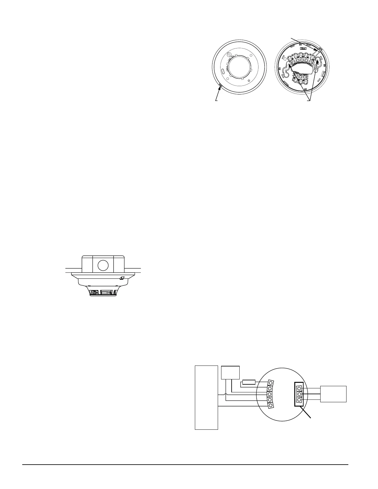
Wiring Diagrams
Figure 3a: Wiring Diagram, 2WTR-B and 2WTA-B
2-WIRE
ZONE
2-WIRE
CONTROL
PANEL
+
–
(
5
)
RA –
(
4
)
RA +
(
3
)
– IN/OUT
(
2
)
+ OUT
(
1
)
+ IN
RA400Z
EOL
RESISTOR
OPTIONAL
RELEASING
DEVICE
(6) NC
(7) C
(8) NO
NOT INCLUDED ON
2WTA-B MODEL
NOTE: FOR ALL COMPATIBLE ADEMCO PANELS,
DO NOT EXCEED 30 OHMS LINE IMPEDANCE.
NOTE: ONLY ONE 2WTR-B DETECTOR PER ZONE CAN BE USED.
S0109-00
S0122-00
S0121-00

 Loading...