LED L-series Indoor Horn Strobes and Strobes — P/N I56-0022-000 8/25/2023 9
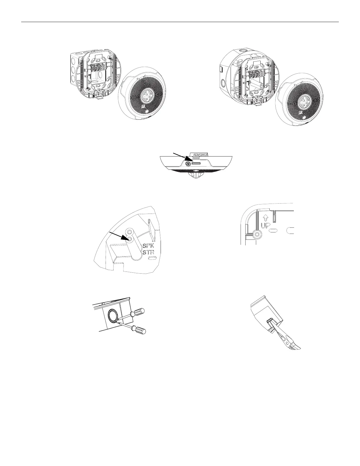
Remove a Ceiling Model Appliance Installation
Figure 12 Mounting a Ceiling Device
(Double-Gang Box)
A0610-00
Figure 13 Surface Mounting a Ceiling Device
(SBBCRL/SBBCWL)
A0609-00
Figure 14 Ceiling Device - Location of Locking Button
A0623-00
Figure 15 Selecting screw location in a ceiling
installation of a surface-mount back box
A0505-01
Figure 16 Surface Mount Back Box “Up” Arrow
Figure 17 Knockout and V500/V700 Removal for Surface Mount Back Box
Strobe devices mount
in location
labeled “STR”
½ inch
or ¾ inch
A0465-01
Figure 17A Knockout size Figure 17B Wire Mold Removal
A0466-01
NOTE: Use caution not to strike the knockout near the top edge of the
wall version of the surface mount back box.