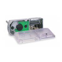
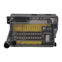
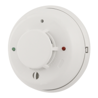
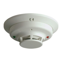
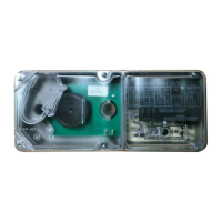
FIGURE 7. SYSTEM WIRING DIAGRAM FOR 4-WIRE DUCT SMOKE DETECTORS:
Do not loop wire under terminals when wiring detectors. Break wire runs to provide system supervision of connections.
24VAC/DC
9 10
AUXILIARY CONTACTS
FOR FAN SHUTDOWN, ETC. (NOTE 2)
16
617
8187
N.O.
C.
N.C.
N.O.
C.
N.C.
16
617
8 18 7
N.O.
C.
N.C.
N.O.
C.
N.C.
SUPERVISORY CONTACTS
(NOTE 3)
24V
9 10
AUXILIARY CONTACTS
FOR FAN SHUTDOWN, ETC. (NOTE 2)
SUPERVISORY CONTACTS
(NOTE 3)
SUP N.O.
SUP C
SUP C
SUP N.O.
4
5
ALARM
INITIATION
CONTACTS
(NOTE 4)
4
5
ALARM
INITIATION
CONTACTS
(NOTE 4)
ALARM
INITIATION
LOOP
UL/FM LISTED
4-WIRE
CONTROL PANEL
+
120
VAC
120
VAC
OR
OR
AUX A
AUX B
AUX A
AUX B
ALARM N.O.ALARM N.O.
ALARM C
ALARM C
3
3
14
14
FIRST DETECTOR IN THE LOOP
POWER INPUTS (NOTE 1) POWER INPUTS (NOTE 1)
LAST DETECTOR IN THE LOOP
EOL RESISTOR
SPECIFIED BY
PANEL
MANUFACTURER
NOTE 1: 24V Power Inputs accept a non-polarized 24VDC or 24VAC 50-60Hz.
120VAC Power Inputs accept only 120VAC 50-60Hz. Connect power source to
appropriate terminals of each detector. See specifications for additional power
supply information.
NOTE 2: Auxiliary contacts shown in standby position. Contacts switch dur-
ing alarm as indicated by arrows. Auxiliary contacts are not to be used for
connection to the control panel. See specifications for contact ratings.
NOTE 3: Supervisory contacts shown in standby position. Open contacts indi-
cate a trouble condition to the panel. See specifications for contact ratings.
NOTE 4: Alarm Initiation contacts shown in standby position. Closed contacts
indicate an alarm condition to the panel. See specifications for contact ratings.
H0558-07
Designation Default Selection Features
TRBL SHUTDN
OFF OFF Aux relay does not switch states with a Trouble condition
ON Aux relay switches states with a Trouble condition
SENSORS
1 1 Only one sensor is connected the Power Board
2
Two sensors are connected to the Power Board
MIN TMPR
DELAY
7 7
Provides a Trouble condition ( terminals 3 and 14 open) when Sensor Housing cover has
been removed or has been secured improperly for more than 7 minutes
0 Provides an instantaneous Trouble condition(terminals 3 and 14 open) upon cover removal
TABLE 2. DIP SWITCH SETTINGS:
[10] DETECTOR STATUS INDICATION
Detector Staus is indicated by the LED sensor, and the correcsponding LED on
the power board. The power board has two separate LED’s to indicate the sta-
tus of each sensor connected to it. Refer to Table 3 on page 8 for more details.
[11] INTERCONNECTION (MULTIPLE FAN SHUT DOWN)
When using the interconnect feature, an alarm from an initiating device will
switch the Aux Relays on the other devices interconnected.
5 I56-2967-008R
21/09/2020
Amended by Pertronic Industries, 21 September 2020 (DST1 not available in Australia and New Zealand)
 Loading...
