D770-17-00 3 I56-986-00
Adjustments To Factory Settings
Table 2.
FACTORY SETTINGS (PSI)
MODEL
Fall
(Low Switch)
Rise
(Hi Switch)
EPS40-1
EPS40-2
EPS120-1
EPS120-2
30± 1.5
30± 1.5
––
105 - 110
105 - 110 120 - 125
––
50± 2.5
Table 3.
FIELD SETTINGS (PSI)MODEL
EPS40-1
EPS40-2
EPS120-1
EPS120-2
10-100
10-100
10-200
10-200
Single-switch Model — EPS40-1 and EPS120-1
1. Install pressure switch as stated in “INSTALLATION”
portion of instruction manual. Attach pressure test
source to system.
2. Back off locking screw (see Figure 1) to allow main ad-
justment wheel to rotate freely.
3. Test the switch for the set point by introducing 40 PSI
pressure from the pressure test source for the EPS40-1
(115 PSI for the EPS120-1). Decrease pressure slowly un-
til the switch trips. Rotate adjustment wheel (counter-
clockwise to increase pressure) and retest by first
introducing a higher pressure than desired and slowly
reducing pressure until the switch trips. Repeat process
until switch trip point is at desired pressure setting. The
approximate sensitivity of the adjustment wheel: 1/2
turn = 11 PSI for the EPS40-1; 1/2 turn = 40 PSI for the
EPS120-1.
4. Retest the set point several times to ensure accuracy of
setting.
5. Re-seat locking screw.
Dual-switch Model — EPS40-2 and EPS120-2
1. Install pressure switch as stated in “INSTALLATION”
portion of instruction manual. Attach pressure test
source to system.
2. Back off locking screw (see Figure 1) to allow main ad-
justment wheel to rotate freely.
3. Option 1: To adjust the nominal setting of the pressure
window (low switch setting to high switch setting) with-
out affecting the size of the window, adjust the main ad-
justment wheel to the desired setting using the pressure
source to verify each switch setting. The approximate
sensitivity of the adjustment wheel: 1/2 turn = 11 PSI
for the EPS40-2; 1/2 turn = 40 PSI for the EPS120-2.
Option 2: To adjust the pressure window size and the
nominal setting of the pressure window, adjust the main
adjustment wheel until the high switch (SW1) trips at
the desired pressure using the pressure test source. De-
crease the pressure until the low switch (SW2) trips.
Note pressure and determine how much change is de-
sired on the low switch. Adjust the 1/4" hex screw to ei-
ther increase (counterclockwise) or decrease
(clockwise) the window size. (The low switch will be af-
fected.) The approximate sensitivity of the hex screw ad-
justment: 1/2 turn = 5 PSI. An approximate maximum
window size of 30 PSI is obtainable within the differen-
tial limits stated on page 1. Retest the high switch after
adjusting the low switch.
4. Retest the set points several times to ensure the accuracy
of the settings.
5. Re-seat locking screw.
NOTE: The sensor assembly is not field replaceable. Do
not attempt to disassemble these parts. If you have
any questions, consult System Sensor. System Sen-
sor recommends careful consideration of the fol-
lowing factors when specifying and installing
Alarm and Supervisory Pressure Switches. Always
refer to the Installation and Maintenance Instruc-
tion for specific recommendations on individual
devices before installing the unit.
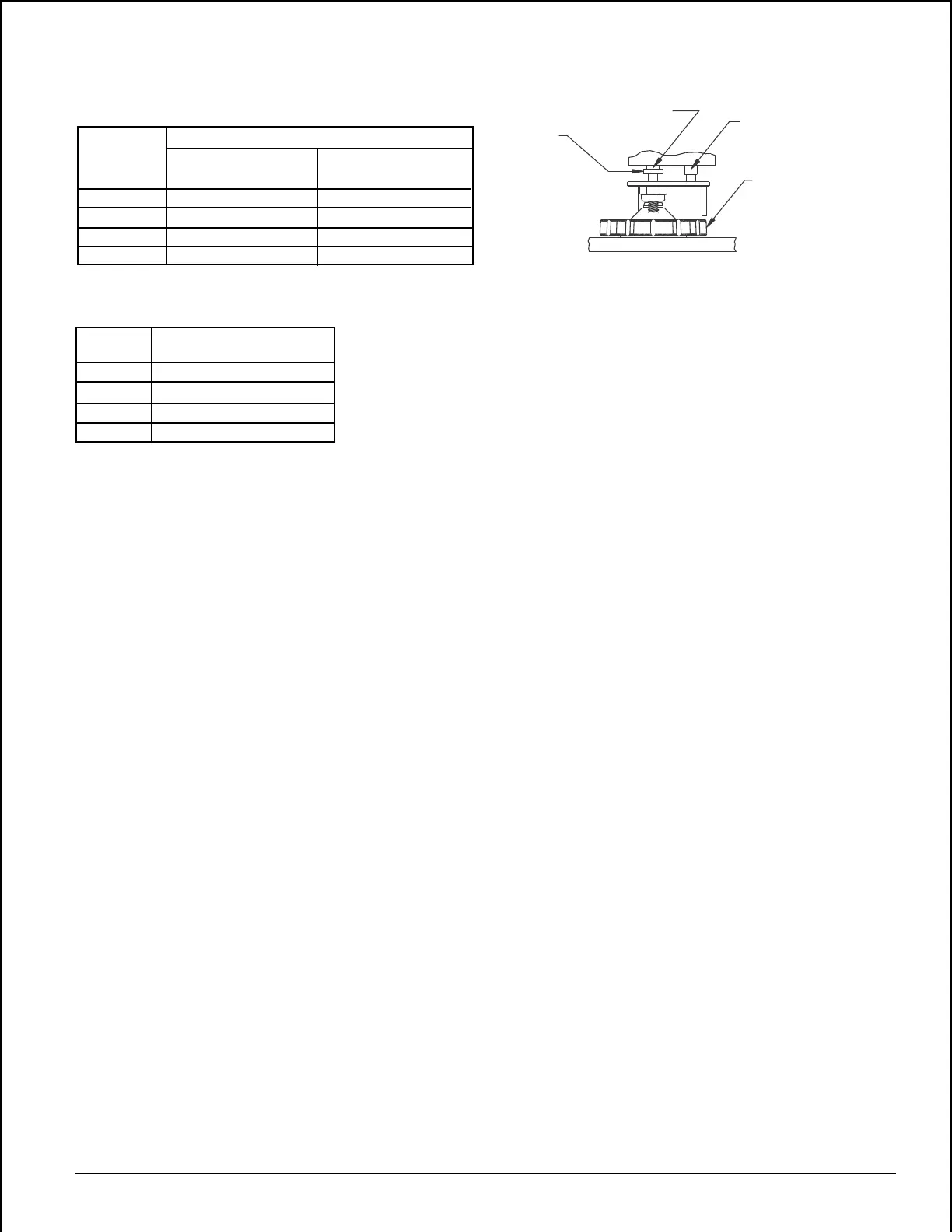
ADJUSTING
SCREW
1/4" HEX HEAD
(NOT PRESENT IN
SINGLE SWITCH
MODELS)
MAIN ADJUSTING WHEEL
(TURN COUNTERCLOCKWISE
TO INCREASE PRESSURE)
SWITCH 2
(LOW SWITCH
EPS40-2 AND
EPS120-2)
SWITCH 1
(HIGH SWITCH
EPS40-2 AND EPS120-2;
LOW SWITCH EPS40-1)
Figure 5. Adjustments (Dual-switch model shown):
A78-2347-00
Technical Manuals Online! - http://www.tech-man.com