D770-17-00 2 I56-986-00
Installation
1. Remove Cover
Cover is held on by two tamper resistant screws. (Re-
moval key is enclosed with pressure switch.)
2. Mounting the Switch
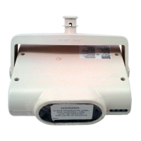
The device is designed to be mounted in the upright po-
sition; side mounting is also acceptable. Locate it where
vibration, shock, and mechanical loading are minimal.
Refer to piping diagram above (Figures 2 and 3).
a. Mount the device directly to the line via the 1/2" NPT
pressure connection. The use of teflon pipe sealant
tape is recommended. Be sure the fitting is tight
enough to prevent leaks.
b. Apply tightening torque to the black plastic hex por-
tion of the device.
A78-2397-00
Figure 3. Typical piping diagram for EPS120-1,
EPS120-2
Figure 2. Typical piping diagram for EPS40-1,
EPS40-2
DRY
PIPE
VALVE
OS & Y
VALVE
WATER
BY-PASS
TEST
VALVE
LOCAL ALARM
SHUT OFF
VALVE
WATER
MOTOR
GONG
CHECK
VALVE
EPS40
CHECK
VALVE
AIR LINE
SHUT-OFF
VALVE
INSTALL
BLEEDER
VALVE FOR
TESTING
EPS10
DRY SYSTEM
WIRE TO SUPERVISORY
CIRCUIT OF FIRE ALARM
CONTROL PANEL
WIRE TO ALARM
INDICATING CIRCUIT
OF FIRE ALARM
CONTROL PANEL
TO
SPRINKLER
SYSTEM
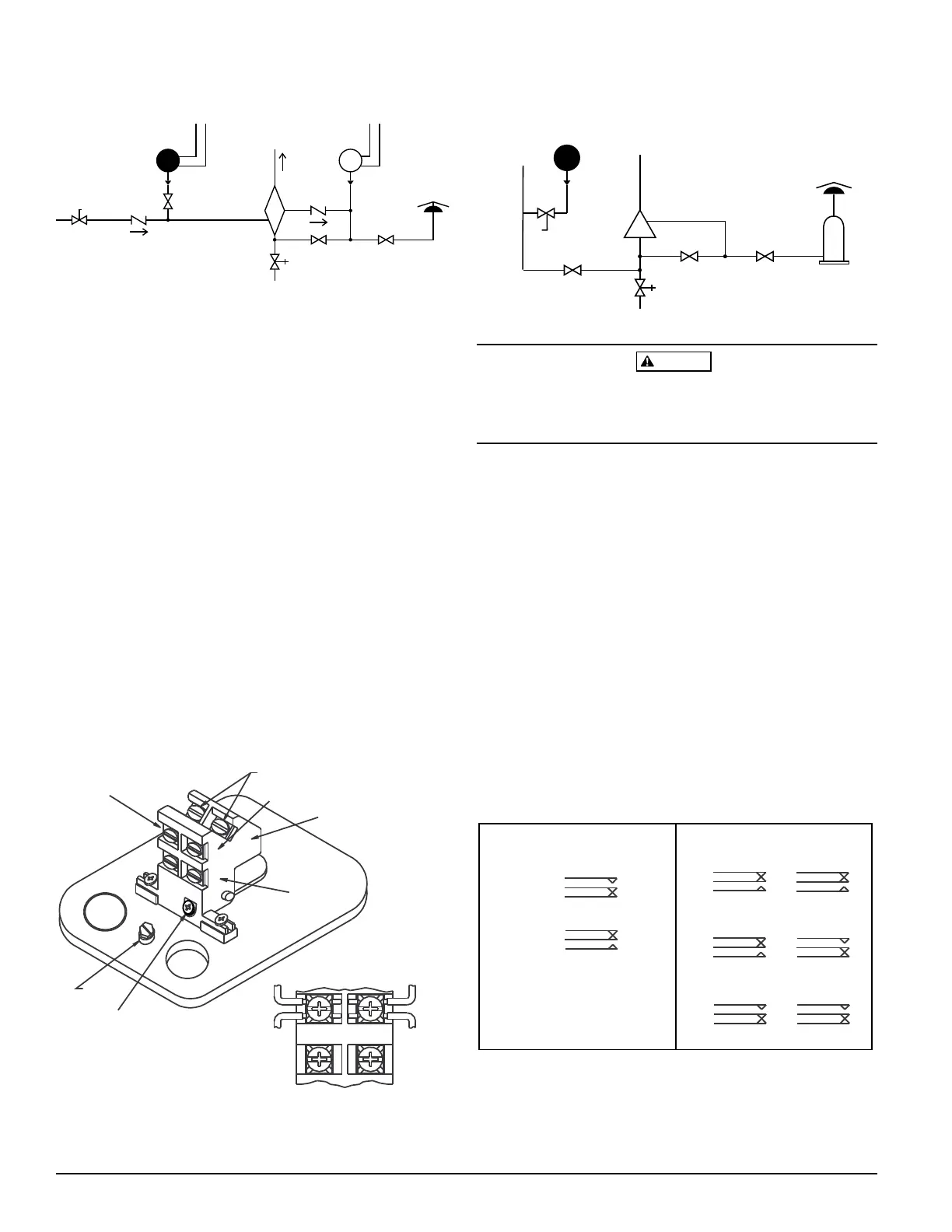
Figure 4. Switch location:
A78-2346-00
Table 1. Electrical connections (referenced at factory
settings):
MODELS EPS40-1, EPS120-1
SWITCH AT NORMAL SYSTEM PRESSURE
SWITCH AT TRIP POINT
B
COM
A
A
COM
B
SWITCH 1
SW2SW1
SWITCHES AT NORMAL SYSTEM PRESSURE
SWITCHES AT LOW TRIP POINT
SW1 SW2
MODELS EPS40-2, EPS120-2
SWITCHES AT HIGH TRIP POINT
SW1 SW2
B
COM
A
B
COM
A
B
COM
A
A
COM
B
A
COM
B
A
COM
B
GROUND
SCREW
COM
B
A
COMMON
TERMINALS
BREAK WIRE AS SHOWN FOR
SUPERVISION OF CONNECTION.
DO NOT ALLOW STRIPPED WIRE
LEADS TO EXTEND BEYOND
SWITCH HOUSING. DO NOT
LOOP WIRES.
SWITCH #1
SWITCH #2
SWITCH #2
LOCKING
SCREW
TERMINAL “A”
TERMINAL “B”
CAUTION
High voltage. Electrocution hazard. Do not handle live AC
wiring or work on a device to which AC power is applied.
Doing so may result in severe injury or death.
3. Wire the device in accordance with the National Electri-
cal Code. Two 7/8" diameter conduit connection holes
have been provided in the mounting plate to accept stan-
dard 1/2" conduit fittings (one is removable knock-out
type). If a NEMA 4/UL 4x (waterproof unit) is required,
waterproof flexible metallic conduit and appropriate
conduit fittings must be used. Recommended connectors
are Thomas and Betts PN 5332 (180° coupling), PN 5352
(90° coupling), and PN 5262 seal ring.
4. Connect wiring to terminals (see Figure 4 and Table 1).
WET
SYSTEM
ALARM
CHECK
VALVE
OS & Y
VALVE
OS & Y
VALVE
WATER
BY-PASS
VALVE
AIR
PRESSURE
SUPPLY
BLEEDER
TEST
VALVE
EPS120
LOCAL ALARM
SHUT OFF
VALVE
RETARD
WATER
MOTOR
GONG
A78-2398-02
Technical Manuals Online! - http://www.tech-man.com