N770-03-00 2 I56-394-05
Section 1
Installation Instructions For Post Indicator Valves
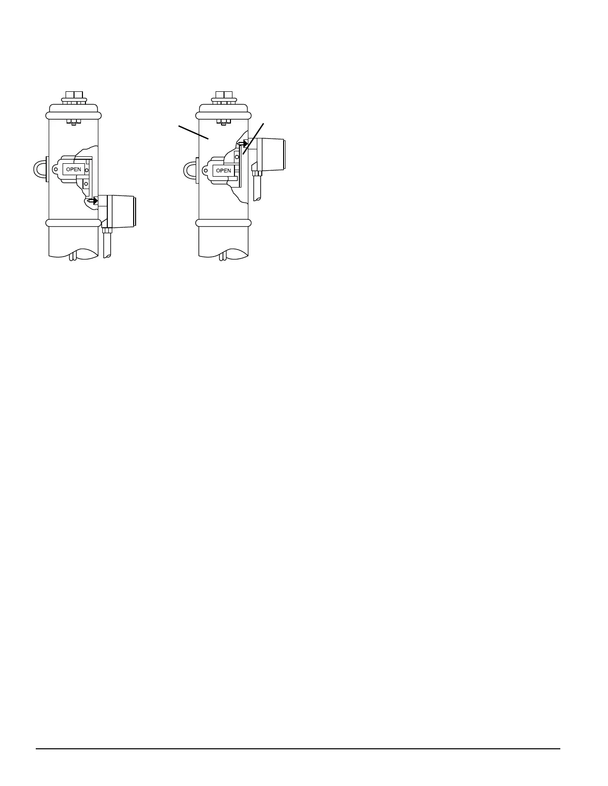
1. There are two types of post indicator valves - rising flag
and falling flag. In a rising flag installation, the PIBV2
mounts below the target assembly, as shown in Figure
2A. Closing the valve raises the target assembly and re-
leases the actuating lever on the PIBV2. In a falling flag
installation, the PIBV2 mounts above the target assem-
bly (Figure 2B). Closing the valve lowers the target as-
sembly and releases the actuating lever on the PIBV2.
The PIBV2 is set for falling flag installation. If a ris-
ing flag operation is desired, it is necessary to re-
verse the action of the switch (See Section 4).
2. If the post indicator valve is predrilled with
1
/2" NPT
mounting hole, remove the plug and go to step 6. If the
post indicator valve is NOT equipped with a
1
/2" NPT
mounting hole, it will be necessary to drill and tap the
hole.
3. Position the valve in the fully open position ("OPEN"
should appear in the window) and remove the head
and target assembly. In doing so, ensure that the as-
sembly can be reinstalled with its original adjustment.
4. (a)In a falling flag installation (flag lowers as valve is
closed), measure the distance from the bottom of the
head to the upper surface of the target that will con-
tact the actuating lever of the PIBV2. Add
3
/32" to this
measurement and mark the outside of the housing at
that location. Drill with a
23
/32" drill bit and tap a
1
/2"
NPT thread.
(b)In a rising flag installation (flag rises as valve is
closed), measure the distance from the bottom of the
head to the lower surface of the target that will con-
tact the actuating lever. Subtract
3
/32" to this measure-
ment and mark the outside of the housing at that
Figures 2A and 2B:
HEAD
TARGET
A78-1629-00 A78-1630-00
Rising Flag
Falling flag
location. Drill with a
23
/32" drill bit and tap a
1
/2" NPT
thread.
5. Replace the head and target assembly.
6. Screw the locknut onto the threaded nipple which is
supplied with the PIBV2.
7. Screw the nipple hand tight into the
1
/2" hole in the
valve and tighten the locknut against the housing to se-
cure the nipple in position.
8. Insert a probe into the hole through the nipple to mea-
sure the distance from the open end of the nipple to the
to the desired position on the target assembly. Subtract
5
/8" from the distance and set the length of the actuat-
ing lever of the PIBV2 from the end of the enclosure to
this distance. Tighten the set screw which holds the ac-
tuating lever.
9. Close the valve 3 to 4 revolutions.
10. Install the PIBV2 onto the nipple and orient the conduit
entry down (See Figure 4). Apply pressure to the PIBV2
and lock the set screws to secure the nipple to the
PIBV2.
11. Slowly open the valve to its fully open position. The
switch should trip as the valve opens, but not force the
actuating lever against the nipple when fully open. To
check for this condition, open the valve fully and de-
press the top of the actuating cam to stretch the actuat-
ing spring further. There should be some additional
movement available. If no movement is available, dam-
age may occur to the PIBV2 actuator lever. It will be
necessary to adjust the flag location by removing the
head and turning the handle while the valve stem is
disengaged (refer to the valve manufacturer.)
12. After checking the fully open position to ensure ad-
equate clearance, close the valve slowly until the
PIBV2 contacts trip. The switches must trip within
1
/5
of the full travel distance of the valve.
13. If the PIBV2 does not change states within
1
/5 of the
length of travel, it may be necessary to adjust the flag
up or down by removing the head and turning the
handle (refer to the valve manufacturer.)
Section 2
Installation Instructions For Butterfly Valves
(See Figure 3)
1. Remove the
1
/2" NPT plug from the gear housing.
2. Loosen 2 set screws that hold the nipple on the PIBV2
and remove the nipple.
3. Screw the locknut onto the nipple.
4. Screw the nipple into the
1
/2" NPT hole and hand
tighten. Tighten the locknut firmly to the housing to se-
cure the nipple.
5. Open the valve fully and close the valve approximately 3
revolutions, noting which direction the target moves.
6. Retract the actuating arm and install PIBV2 onto the
Technical Manuals Online! - http://www.tech-man.com