Electrical connection |
7
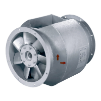
Table 3 Description of electrical connections of the following fans: AW 200 EC sileo (#35854), AW 250 EC sileo
(#35855), AW 300 EC sileo (#35857), AW 350 EC sileo (#35859)AW 400 EC sileo (#35860), AW 450 EC sileo
(#35863)
Wire
no.
Connection Color
Function/assignment
CON10 L
black or
brown
Power supply, see name plate for voltage range
CON11 N
blue Neutral conductor
CON12 PE
green/
yellow
Protective conductor
1 GND
blue GND-connection of the controller interface
2 0...10 V PWM
yellow Controller input 0...10 V or PWM
3 10 V
red
Voltage output 10 V / Short-circuit-proof power supply for external
devices (e.g. poti)
I max=1.1mA:
AW 200 EC sileo (#35854)AW 250 EC sileo (#35855), AW 300 EC sileo
(#35857), AW 450 EC sileo (#35863)
I max=10mA:
AW 350 EC sileo (#35859)AW 400 EC sileo (#35860)
4
Tacho*
white
Speed output: Open Collector, 1 impulse per revolution, electrically
isolated, Isink_max = 10 mA
NC*
white 1
Status relais, open for failure
COM*
white 2
* Not available with every device
Client side
Max. speed
Adjustable speed
10V –> n = max
1V –> n = min
<1V –> 0
Adjustable speed through PWM
1...10 KHz
100 % PWM –> n = max
10 % PWM –> n = min
< 10 % –> 0
Adjustable speed through potentiometer
| 003
 Loading...