This document provides installation and operating instructions for Systemair Axial Fans, specifically the AW and AR series. These fans are designed as built-in devices for conveying air according to their technical data.
Function Description
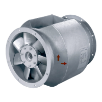
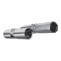
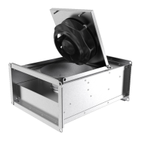
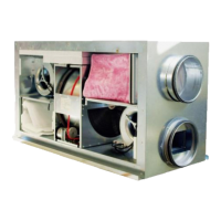
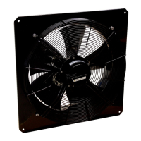
Systemair axial fans of the AR and AW series are primarily used for air conveyance. They are available in various configurations, including models with wall plates (AW series) and round casings (AR series) conforming to Eurovent 1/2. The fans can be equipped with different motor types, such as electronically commutated (EC) motors (1-phased or 3-phased), and various poled motors (2, 4, or 6 poled) that can be controlled by frequency converters or voltage. Some models also feature voltage-controllable motors.
The fans are designed to operate within specified ranges for maximum transported air temperature, maximum ambient temperature, and sound pressure, as detailed in their respective data sheets available in the online catalog. They handle specific voltage, current, enclosure class, and weight, which are indicated on the nameplate. Motor-specific data can be found on the motor's nameplate or in the manufacturer's technical documents.
Important Technical Specifications
The nameplate provides crucial technical details:
- Type Designation: e.g., AW 200E2 sileo.
- Voltage/Frequency/Current/Power/Fan Impeller Speed: Specifies the electrical requirements and operational speed. For example, 220-230V~ 50/60Hz, 0.30/0.34A, 64/78W, 2600/2900min⁻¹.
- Capacity/Capacitor Voltage: For models requiring a capacitor, its capacitance and voltage rating are listed (e.g., 1.5µF 450VDB).
- Moisture Protection: Indicates the level of protection against moisture.
- Insulation Class: Specifies the electrical insulation rating.
- Article No.: Unique identifier for the product.
- Certifications: Lists relevant certifications like CE and EAC.
The type key further breaks down the fan's characteristics:
- Size: Numeric value indicating the fan's size (e.g., 200).
- Motor Type:
- EC: Electronically commutated (1-phased or 3-phased).
- E2, E4, E6: 2, 4, or 6 poled, controllable by frequency converter (1-phased).
- DV, DS: 4 or 6 poled, voltage controllable (3-phased).
- EZ, EV, ES: 2, 4, or 6 poled, voltage controllable (1-phased).
- D4, D6: 4 or 6 poled, controllable by frequency converter (3-phased).
- Fan Type:
- AW: Axial fan with a wall plate.
- AR: Axial fan with a round casing according to Eurovent 1/2.
- Motor Version: -L for large motor version, otherwise normal motor version.
Electrical connections vary by model. For AW 200-450 EC sileo fans, connections include:
- CON10 (L): Power supply (black or brown).
- CON11 (N): Neutral conductor (blue).
- CON12 (PE): Protective conductor (green/yellow).
- 1 (GND): GND-connection of the controller interface (blue).
- 2 (0...10 V PWM): Controller input (yellow).
- 3 (10 V): Voltage output for external devices (red), with max current varying by model (1.1mA for smaller models, 10mA for larger ones).
- 4 (Tacho*): Speed output (white), open collector, 1 impulse per revolution, electrically isolated, Isink_max = 10 mA.
- **NC*, COM*: ** Status relay (white 1, white 2), open for failure.
For AW 500-560D EC sileo fans, connections include:
- PE: Protective conductor.
- L1, L2, L3 (KL1): Power supply (for 3-phase motors).
- N, L* (KL1): Power supply (for 1-phase motors, e.g., AW 500 EC sileo #35865).
- 1 (NC), 2 (COM), 3 (NO) (KL2): Status relay contacts (open for failure, changeover contact, close for failure).
- 1 (OUT): Analog output (0-10 VDC, max. 3 mA, SELV) for current motor modulation level.
- 2, 8 (GND): GND-connection of the controller interface.
- 3, 7 (0...10 V PWM): Analog input 1 (0-10 V, Ri = 100 kΩ, adjustable curve, SELV).
- 4 (+10 V) (KL3): Voltage output 10 VDC (+/- 3%), max. 10 mA, for external devices.
- 5 (+20 V): Voltage output 20 VDC (+25%/-10%), max. 50 mA, for external devices.
- 6 (4-20 mA): Control/current sensor value input (4-20 mA, impedance 100 Ω, SELV).
- 9, 11 (RSB), 10, 12 (RSA): RS485 interface for MODBUS.
For AW 630D-1000D EC sileo fans, connections include:
- PE: Protective conductor.
- L1, L2, L3 (KL1): Power supply.
- 3 (NC), 2 (COM), 1 (NO) (KL2): Status relay contacts.
- 1 (RSB), 2 (RSA), 3/10 (GND): RS485 interface for MODBUS and GND.
- 4 (Ain1 U), 6 (Ain1 I): Analog input 1 (0-10 V or 4-20 mA, Ri = 100 kΩ or 100 Ω, adjustable curve, SELV).
- 5 (+10 V): Fixed voltage output 10 VDC (+/- 3%), max. 10 mA.
- 7 (Din1): Digital input 1 (enable electronics, reset function).
- 8 (DIN2): Digital input 2 (switching parameter sets 1/2).
- 9 (DIN3): Digital input 3 (controller's direction of action).
- 11 (Ain2 U), 13 (Ain2 I): Analog input 2 (0-10 V or 4-20 mA, Ri = 100 kΩ or 100 Ω, adjustable curve, SELV).
- 12 (+20 V): Fixed voltage output 20 VDC (+25%/-10%), max. 50 mA.
- 14 (Aout): Analog output (0-10 VDC, max. 5 mA, SELV) for current motor modulation level.
Usage Features
- Intended Use: Systemair axial fans are exclusively designed as built-in devices for conveying air according to their technical data.
- Incorrect Use: Prohibited uses include conveying abrasive, explosive, combustible air or air with solid particles; operation in an explosive atmosphere; installation outdoors without weather protection; operation without a duct system or protection grille; and operation with closed air connections.
- Installation: The fan can be installed in any mounting position. Proper installation requires checking the load-bearing capacity of the surface, considering all static and dynamic loads, and ensuring sufficient space. It is crucial to prevent foreign bodies from being drawn in and to provide contact and intake protection with safety distances according to DIN EN ISO13857 and DIN 24167-1. Flexible connections are recommended to reduce vibration transmission. Straight ducts of at least 2.5 times the nominal diameter (for round ducts) or hydraulic diameter (for rectangular ducts) are required before and after the fan to ensure smooth and constant airflow and prevent damage to bearings.
- Electrical Connection: Connections must adhere to specified regulations for voltage, current, and insulation. Protective earth must always be connected first. For EC motors, motor protection is integrated. For AC motors, external motor protection switches are necessary. Shielded cables are recommended for variable-speed fans, and all components (fan, frequency converter, motor) must be grounded. Sinus filters are recommended, and running the fan below 10 Hz via a frequency converter should be avoided.
- Commissioning: Before commissioning, a thorough check for visible damage, proper electrical connection, and functioning protective equipment is required. The direction of rotation/conveyance, smooth running, current consumption, and tightness of all connections must be verified.
- Operation: The device should only be operated by adequately qualified personnel, adhering to system-related conditions and requirements. Safety elements must not be dismantled or circumvented.
Maintenance Features
- Warranty: Warranty claims are contingent on correct operation, adherence to data sheets, a completed maintenance plan, and a commissioning report.
- Storage: Fans should be stored in original packaging in a dry, dust-free, weather-protected location, avoiding extreme heat or cold. Long-term storage (over 1 year) should be avoided to prevent motor bearing issues.
- Troubleshooting: A detailed troubleshooting table is provided for common issues such as impeller imbalance, soiling, wrong rotation direction, vibrations, high pressure losses, blockages, missing phases, motor overheating, and capacitor issues. Remedies range from rebalancing and cleaning to checking wiring, optimizing line routing, and contacting Systemair.
- Maintenance Plan: Regular maintenance is crucial for continuous fan operation. The operator is responsible for creating a maintenance plan that documents activities like cleaning, replacing defective components, and other corrective measures. Maintenance intervals are specified for normal and extreme operating conditions (e.g., kitchen exhaust fans, stall fans).
- Every six months (normal conditions): Check for visible damage, corrosion, contamination, impeller damage/imbalance, condensate drain function, fan intake freedom, correct component usage, and current consumption.
- Annually (normal conditions): Clean the fan/ventilation system, check screwed connections, vibration dampers, electrical and mechanical protective equipment, rating plate legibility, and flexible connectors.
- Quarterly (extreme conditions): Clean the fan/ventilation system.
- Every six months (extreme conditions): Check for visible damage, corrosion, contamination, impeller damage/imbalance, condensate drain function, fan intake freedom, correct component usage, and current consumption.
- Cleaning: Cleaning should only be performed by qualified personnel with protective equipment, and the impeller must be at a standstill. It is important to avoid steel brushes, sharp-edged objects, high-pressure cleaners, and bending fan blades. Balance weights on the impeller must be preserved.
- Spare Parts: Only original Systemair spare parts should be used. Serial numbers from the nameplate are required when ordering.
- Deinstallation/Dismantling: Deinstallation and dismantling should be performed in the reverse order of installation and electrical connection.
- Disposal: Materials should be recycled according to national regulations. The fan and packaging are largely made from recyclable raw materials and should be disassembled into components, separating reusable materials from other material groups (metal, plastics, electrical parts).