22
Freshman Series - Owner's Manual - Installation, Operation, and Service Instruction - Version 1.1 EN
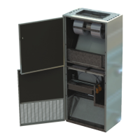
6.4 Electrical Connections
It is recommended that each unit be installed on a permanent, separate electrical
circuit. The circuit must be protected by a fuse or HACR type circuit breaker.
To minimize risk, the unit is equipped with a door switch to disable the 24 VAC
control voltage, de-energizing the internal contacts when the main access panels
are removed. All units without electric heat contain an internal circuit breaker that
interrupts supply line voltage. It is located inside the unit on the main electrical
control box.
In Canada, the unit must be installed and electrically grounded in accordance with
local codes, or the Canadian Electric Code CSA C22.1. In the U.S. installation must
be in accordance with the most current issue of the National Electric Code ANSI/
NFPA 70.
Attention: Electrician
supply to the unit before
repair or major service.
Failure to do so may result in
personal injury.
6.5 Wall Sleeve
Wall sleeves are typically shipped knocked down and must be eld assembled.
Before proceeding, the wall opening must be prepared in accordance to the instal-
lation drawings, relative to the nal installed position of the unit. It will likely be
necessary to provide a support header across the top of the opening to comply
with local building code requirements.
1. Prior to assembly, it may be necessary to trim the depth of the wall sleeve to
suit the nished wall thickness. If the nished wall depth is greater than that
of the wall sleeve or if the unit has a rear standoff, it may be necessary to add
extensions to the sleeve and dividers, which must be fabricated in the eld.
2. Assembly of the wall sleeve is detailed in the assembly drawings enclosed in
the information package provided with the unit ventilator. We recommend
the use of ½” x #10 round head self tapping sheet metal screws to fasten
each component together. Screws must be installed with heads out to prevent
them from catching in the rough wall opening during installation.
3. To assure a tight seal between the wall sleeve and the unit ventilator, apply
foam tape to the mounting anges of sleeve and dividers.
4. Insert the wall sleeve through the rough wall opening from the inside of the
building and secure it into place.
NOTE:
DO NOT install the
exterior louver until
after the Air Handler is
fastened securely to
the wall.
NOTE:
Be careful not to insert
screws where they
may interfere with the
insertion of the Exterior
Louver. Do not insert
screws into the bottom
pan of the wall sleeve
as this may allow water
to seep into the wall
cavity.
Installation Guide
was sent with the Unit for exact measurements, descriptions and installation details.
 Loading...