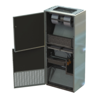
Do you have a question about the SystemAir changeair Freshman Series and is the answer not in the manual?
| Brand | SystemAir |
|---|---|
| Model | changeair Freshman Series |
| Category | Air Handlers |
| Language | English |
Indicates the general safety alert symbol used to signal potential personal injury.
Explains the meaning of DANGER, WARNING, and CAUTION terms for hazardous situations.
Illustrates and explains specific hazard symbols for burn, rotating blades, and hazardous voltage.
Provides unit certification details and recommends installation by qualified technicians.
Instructs on inspecting the unit for freight damages and filing claims if necessary.
Provides fields to record essential unit reference information for future use.
Details the 14-month warranty for standard parts, covering defects in material and workmanship.
Specifies a 3-year warranty for Belimo actuators against material and workmanship defects.
Covers the gas heat exchanger for 5 years against defects under normal use and maintenance.
Describes options for extended warranties on components or the complete unit, including labor.
Outlines conditions and situations where warranties do not apply and disclaims other warranties.
Details the step-by-step process for submitting and processing a warranty claim.
Explains the coding system used to identify unit specifications through its model number.
Emphasizes the importance of preventative maintenance for unit economy and dependability.
Provides instructions for cleaning the exterior and interior of the classroom unit.
Details procedures for cleaning or changing air filters to maintain unit performance.
Step-by-step guide for safely removing and reinstalling the supply fan motor and assembly.
Instructions on how to properly clean the blades and housing of supply and relief fans.
Guidance on cleaning heating and cooling coils, including necessary precautions.
Procedure for cleaning the washable filters used in the energy recovery system.
Instructions for safely removing fixed core plates to access internal components.
Steps for cleaning fixed core plates using compressed air, emphasizing safety.
Detailed steps for removing and reinstalling the relief fan motor assembly.
Procedure for cleaning the energy recovery wheel, including recommended cleaning agents.
Guidance on selecting a suitable location and inspecting the installation site for utilities.
Provides essential minimum clearances for outdoor and indoor installation and service.
Instructions for assembling and installing the unit, including handling heavy components, sealing, and important notes.
Provides essential electrical connection guidance for electricians, including safety notices.
Details the field assembly and installation of wall sleeves, including sealing and screw placement.
Illustrates general assembly of wall sleeves for relief air and standard ventilation.
Instructions for installing the exterior louver into the wall sleeve, noting condensate drain lines.
Explains the use and installation of a relief damper assembly for static pressure control.
Provides a visual guide for the correct installation process of the relief damper.
Instructions for assembling and installing the Rear Standoff (RSO) accessory.
Guidance on unpacking, preparing, and installing the top plenum assembly.
Instructions for installing the pre-assembled Rear Plenum Assembly (RPA).
Steps for unpacking and installing the top duct cover.
Installation drawing for Freshman CA H 1000A NA VP DD, showing rear, right side, and back views.
Installation drawing for Freshman CA H 1000A NA VPS DD, detailing rear, right side, and back views.
Installation drawing for Freshman CA H 1600A NA VP DD, with rear, right side, and back views.
Installation drawing for Freshman CA H 1600A NA VPS DD, showing rear, right side, and back views.
Provides guidance for addressing operational problems with the unit, recommending qualified technicians.
Guides users on diagnosing and resolving issues related to unit controls and mechanical components.
Explains that unit control is typically managed by an external thermostat or control system.
Details the functions of internal controls like temperature sensors, economizer boards, and fan motor protection.
Describes typical unit operation sequences for occupied, unoccupied modes, cooling, and heating.
Lists common problems like tripped breakers, fan issues, noise, and damper operation with solutions.
Addresses specific cooling system problems such as low temperature drop, iced coils, and compressor cycling.
Provides information on how to order replacement parts, including required details and contact information.



 Loading...