27
Freshman Series - Owner's Manual - Installation, Operation, and Service Instruction - Version 1.1 EN
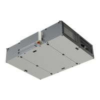
6.13 Top Duct Cover
1. Carefully unpack the top duct cover.
2. Remove the front access covers from the appropriately
selected top duct cover.
3. Place the back/side portion of the top duct cover on top
of the unit and against the wall using screws. (It will be
necessary to push back the insulation to access the bare
metal to start the screws.)
4. Fasten the bottom edges of the cover to the top of the
unit using screws.
5. Complete and test all service connections (electrical,
plumbing, refrigeration, etc.) required for the air handlers
operation.
6. Reinstall the front access cover of top duct cover.
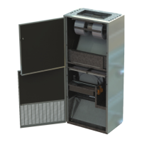
4. Position the Classroom Air Handler directly in front of its
nal installation position. Allow enough room behind the
unit for the RPA and some room to work. (Once the RPA
is mounted it may become more difcult to relocate the
unit.)
5. Place the RPA tight against the back of the unit so that it
is ush with the sides and top of the unit, as shown in the
installation drawings.
6. Begin by fastening the RPA to the back of the unit at one
of the top corners. Place a screw through the 1” front
mounting ange of the RPA side panel into the back of the
unit. Proceed by similarly placing a screw into the opposite
top corner and then down both of the RPA side anges at
approximately 18” apart. (Do not mount the RPA to the
unit through the top or bottom cover of the RPA as these
may interfere with the removal of components during
future service maintenance.)
7. Reinstall the back panel and apply 1”' low density foam
tape (supplied with RPA) around the perimeter of the back
panel of the RPA. This provides ller between the RPA
and the wall surface.
8. If the unit has a cooling coil and drain pan, pass the drain
hoses that come out the back of the unit through the RPA.
These hoses must gravity drain downward to the outside
or to a drain. They must allow condensate to drain freely
to the outside without restriction and without inhibiting
the operation of the dampers. (It will be necessary to cut
away enough of the bird screen in the back of the exterior
louver to allow the condensate hoses to pass between the
blades of the louver to the exterior.)
6.12 Rear Plenum Assembly (RPA) - continued
Installation Guide
was sent with the Unit for exact measurements, descriptions and installation details.
 Loading...