26
Freshman Series - Owner's Manual - Installation, Operation, and Service Instruction - Version 1.1 EN
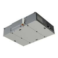
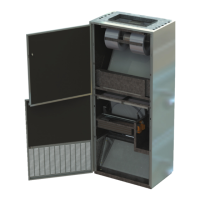
6.11 Top Plenum
1. Carefully unpack the plenum assembly. The plenums sent
with the units may vary in height or model, and will be
labeled with a UV# if provided.
2. Remove the front access covers from the appropriately
selected ve-sided plenum assembly.
3. Apply 3/8” foam tape to the bottom edges of the top
plenum and front access cover to create a positive air
seal between the plenum and the unit. (If your unit does
not have a rear plenum extension apply the foam tape
to the back corners of the plenum where it will meet the
wall.)
4. Place the back/side portion of the plenum assembly
on top of the unit and against the wall or rear plenum
extensions. If applicable, fasten the back corners of
the plenum to the standoff extensions using ¾” x #10
screws. (It will be necessary to push back the insulation
to access the bare metal to start the screws.)
5. Fasten the bottom edges of the plenum to the top of the
unit using ½” x #10 screws.
6. Complete and test all service connections (electrical,
plumbing, refrigeration, etc.) required for the unit opera-
tion.
7. Reinstall the front/ top access cover of ve-sided plenum
assembly.
8. If your plenum is supplied with supply grilles, it may be
necessary to adjust the supply grilles. If the grilles are
double deective (standard) the rear blades of each
grille should be positioned parallel to the oor or slightly
downwards. The front blades should be positioned to
provide a broad spectrum of air dispersion throughout
the room. (Left, right and center)
NOTE:
At this time, it may be easiest to cut any
necessary holes or service knockouts that
may be required in the plenum and install
any plenum takeoffs or supply grilles before
proceeding.
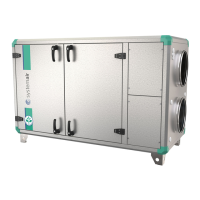
6.12 Rear Plenum Assembly (RPA)
We recommend the use of ¾” x #10 round head self-tapping
sheet metal screws to fasten this accessory to the air handler.
The rear plenum assembly is pre-assembled to minimize eld
installation procedures. These have been shipped separate of
the units to facilitate shipping and on site handling of the units
due to their weight and size. Match up the RPA to the corre-
sponding unit before proceeding.
1. It is necessary to remove and reassemble the back from
the RPA in order to fasten it to the back of the unit. Re-
move the back panel of the RPA.
2. Field cut openings must be made in the back panel of
each rear plenum assembly (RPA). These holes must
directly line up with the wall sleeve openings and must be
sized so as not to restrict airow and still maintain a seal
between the unit and the wall.
3. To assure a tight seal between the classroom unit and the
RPA, apply 3/8” foam tape to the 1” wide front edges of
the RPA and any partitions it may have.
You may require assistant's help for this
procedure.
NOTE:
When a partition (or partitions) is designed
into the RPA and wall sleeve, a separation of
air between two or more air paths must be
maintained from the back of the unit to the
backside of the exterior louver. (refer to job
specic shop or installation drawings)
Installation Guide
was sent with the Unit for exact measurements, descriptions and installation details.
NOTE:
Keep the tape back from the outside edges
by at least ¼” so the tape does not become
unsightly when compressed.
 Loading...