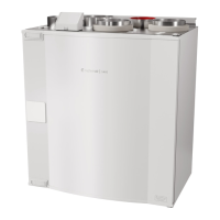
Do you have a question about the SystemAir Danvent DV and is the answer not in the manual?
Details on base frame assembly for units size 10-40 with 150 mm height and lengths from 720-2420mm.
Details on base frame assembly for units size 10-40 with 150 mm height and lengths from 2420-4590mm.
Details on base frame assembly for units size 10-40 with 150 mm height and lengths from 4590-6200mm.
Details on base frame assembly for units size 50-150 with 150 mm height and lengths from 720-2420mm.
Details on base frame assembly for units size 50-150 with 150 mm height and lengths from 2420-4590mm.
Details on base frame assembly for units size 50-150 with 150 mm height and lengths from 4590-6200mm.
Details on base frame assembly for units size 10-40 with 250 mm height and lengths from 720-2420mm.
Details on base frame assembly for units size 10-40 with 250 mm height and lengths from 2420-4590mm.
Details on base frame assembly for units size 10-40 with 250 mm height and lengths from 4590-6200mm.
Details on base frame assembly for units size 50-150 with 250 mm height and lengths from 720-2420mm.
Details on base frame assembly for units size 50-150 with 250 mm height and lengths from 2420-4590mm.
Details on base frame assembly for units size 50-150 with 250 mm height and lengths from 4590-6200mm.
Instructions for mounting rails on units of size 10, 15, 20, and 25 for steel roof installation.
Instructions for mounting rails on units of size 30 and larger for steel roof installation.
Guidelines for ensuring sufficient roof overhang along the long sides of the unit.
Method for calculating roof overhang at the unit ends and mounting overhang profile G1.
Procedure for placing foam bands between rails and roof plates during installation.
Instructions for applying foam bands between roof plates for water resistance.
Guidance on mounting roof plates, noting overlaps required for optimal roof length.
Procedure for mounting the G5 roof overhang profile on the opposite end of the unit.
Instructions for mounting side profiles and corners to protect roof edges.
Steps for sealing plate joints with silicone to prevent water ingress.
Information on the speed control system for the rotor, including DIP switch settings.
Guide for selecting the correct signal using the 4 DIP switch levers for rotor speed.
Instructions for assembling the Systemair casing for specific DV unit models.
Detailed steps for assembling the divided rotor for DV 190 and DV 240 units.
Guidance on rotor mounting when there is limited space above the unit.
Description for mounting horizontal rotors, including housing and frame fastening.
Instructions for mounting center and circumferential gaskets on the rotor.
Final checks and control works after rotor installation, including leakage and belt tension.
Overview of the DVU section, a stand-alone cooling compressor system.
Details on the DVU-internal controller, its LEDs, and operation modes.
Guide on how to navigate and select menus using the controller's potentiometer.
Instructions for changing parameters via the controller's potentiometer.
Procedure for manual operation of the system for testing and maintenance.
Information on necessary software modifications for the Danfoss frequency converter.
Data on cooling capacity, power consumption, and EER factor for compressors.
Information found on the cooling unit's data plate.
Description of the DVU-C unit with cooling recovery features.
Diagrams and explanations for connecting fan motors in Delta and Star configurations.
Factory settings for Danfoss FC101 frequency converter for DV-units with AC motors.
Systemair factory setup for AC-fan operation without thermistor for Danfoss FC101.
Systemair factory setup for Danfoss FC101 for DV-units with PM motors.
| Brand | SystemAir |
|---|---|
| Model | Danvent DV |
| Category | Air Handlers |
| Language | English |
