EasyManua.ls Logo

SystemAir fantech SHR 150R User Manual

SystemAir fantech SHR 150R
40 pages
To Next Page IconTo Next Page
Page #1 background imageLoading...
Page #1 background image
Your ventilation system should be installed in conformance with the appropriate provincial requirements or, in the absence of
such requirements, with the current edition of the National Building Code, and / or ASHRAE’s “Good Engineering Practices”.
Fantech reserves the right to modify, at any time and without notice, any or all of its products’ features, designs,
components and specifications to maintain their technological leadership position.
Please visit our website fantech.net for more detailed technical information.
United States
10048 Industrial Blvd., Lenexa, KS, 66215
Tel.: 800.747.1762
Canada
50 Kanalflakt Way, Bouctouche, NB, E4S 3M5
Tel.: 800.565.3548
SHR 150R
Heat Recovery Ventilator
Installation and Operation Manual
Item #: 427740
Rev Date: 2020-01-22
PARTS IN THE BOX
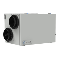
Heat Recovery Ventilator, 1 pc
Hanging Chain Kit, 1 pc
Hardware Kit, 1 pc
Drain Hose Kit, 1 pc
Operation and Installation Manual, 1 pc
Questions and Answers:

SystemAir fantech SHR 150R Specifications

General IconGeneral
BrandSystemAir
Modelfantech SHR 150R
CategoryHeating System
LanguageEnglish

Summary

DETERMINING YOUR AIRFLOW REQUIREMENT

Room Count Method

Method for calculating ventilation needs based on room count and type.

ASHRAE method

Ventilation calculation based on floor area and number of bedrooms.

INSTALLATION EXAMPLES

FULLY DEDICATED SYSTEM

System drawing stale air from exhaust areas and supplying fresh air to living areas.

HRV ducting for fully Dedicated System

Illustrates ducting configuration for a fully dedicated system installation.

INSTALLATION EXAMPLES (CONT'D)

PARTIALLY DEDICATED SYSTEM (BETTER)

Connects HRV fresh air to furnace return plenum, stale air from key areas.

HRV/Furnace ducting for Partially Dedicated System

Shows ducting for connecting HRV to a furnace's return air plenum.

INSTALLATION EXAMPLES (CONT'D)

SIMPLIFIED INSTALLATION (GOOD) (RETURN/RETURN METHOD)

Connects HRV supply and exhaust streams to furnace cold air return.

HRV/Furnace ducting for Simplified Installation - Option 1

Illustrates ducting for simplified installation connecting to furnace cold air return.

EXTERIOR DUCTING INSTALLATION

WEATHERHOOD LOCATION

Guidelines for positioning intake and exhaust weatherhoods on exterior walls.

INSTALLING THE DUCTING TO THE WEATHERHOODS

Instructions for connecting flexible insulated duct to weatherhoods.

STEPS FOR HOOD INSTALLATION

Step-by-step guide for physically installing exterior hoods.

INTERIOR DUCTING INSTALLATION

Installing ducting to HRV

Method for connecting flexible or solid ducting to the HRV unit.

Supply air grilles location

Recommendations for locating supply air grilles in different home types.

Exhaust air grilles location

Recommendations for locating exhaust air grilles in areas with poor air quality.

HRV INSTALLATION

LOCATION

Criteria for selecting an appropriate installation location for the HRV unit.

Mounting- Chain mount

Detailed steps for mounting the HRV unit using a chain system.

INSTALLING DRAIN LINE

Start up procedure

Steps to follow for initiating the HRV unit after installation.

Airflow balancing

Procedure to ensure equal supply and return airflow for optimal operation.

Airflow balancing (Cont'd)

Adjusting airflows

How to adjust the integrated damper for desired airflow.

Measuring the airflow using station (grid) method

Method and tools for measuring airflow velocity using a measuring station.

Low Voltage Control Systems

CENTRAL CONTROLS

Overview of primary control systems for the HRV unit.

AUXILIARY CONTROL

Description of secondary or supplemental control devices for the HRV.

WIRING DIAGRAM - SHR150R

LEGEND

Key to understanding symbols and abbreviations used in the wiring diagram.

NOTES

Crucial notes regarding wiring, fuses, and polarity for installation.

WIRING DIAGRAM (CONT'D)

WIRING DIAGRAM TO FURNACE

Wiring connections between the HRV and a furnace system.

FOR A FURNACE CONNECTION TO A COOLING SYSTEM:

Details for wiring the HRV when connecting to a furnace with cooling capabilities.

TROUBLESHOOTING

Air is too dry

Identifies causes and solutions for excessively dry indoor air.

Air is too humid

Identifies causes and solutions for excessively humid indoor air.

Persistent condensation on window

Addresses causes and solutions for condensation forming on windows.

Poor Air Flows

Discusses issues related to insufficient or restricted airflow within the system.

Supply air feels cold

Explains why supply air might feel cold and how to resolve it.

HRV and/or Ducts frosting up

Addresses the causes and solutions for frost accumulation on the HRV or ducts.

Condensation or Ice Build Up in Insulated Duct to the Outside

Solutions for ice or condensation forming in the outdoor insulated ductwork.

LED is flashing

Troubleshooting steps when the unit's LED indicator is flashing.

LED is not flashing

Troubleshooting steps when the unit's LED indicator is not illuminated.

HRV MAINTENANCE CHART

Limited Warranty

Details the warranty coverage, limitations, and responsibilities for the HRV unit.

Related product manuals