4
| Technical Data
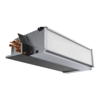
3.2 Connections Left and Right models
Fig. 3 Duct connections
Position Description
R
Right hand model (Supply air connection is situated on the right hand side of the unit
viewed from the front)
L
Left hand model (Supply air connection panel is situated on the left hand side of the unit
viewed from the front)
Symbol
Description
Symbol
Description
Supply air
Outdoor air
Exhaust air
Extract air
3.3 Installation recommendation regarding condensation
3.3.1 Condensation inside of the unit
The unit should run continuously. If the unit is intended to be stopped by the user manually or due to calendar function
we recommend to install air tight dampers at extract and supply air ducts. The dampers will ensure that no air circulates
from the warm parts of the building through the unit to outside (chimney effect). If no dampers are installed there is risk
of condensation inside the unit and the outdoor ducts during these stop periods. It also might be that cold air from out-
side could pass the unit and enter into the building. That could cause condensation outside the supply and extract air
ducts and even at the valves in the rooms.
When the unit is not running due to late commissioning in winter time, the supply and extract air ducts should be dis-
connected and closed due to above mentioned effects until commissioning and regular operation.
333569 | v1.1

 Loading...