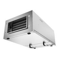
Do you have a question about the SystemAir SYSCOIL COMFORT 10 and is the answer not in the manual?
Instructions for safe installation, commissioning, use, and maintenance by qualified personnel.
Key warnings regarding power supply, hydraulic connections, and oil compatibility for safe operation.
Environmental and water circuit operating limits including temperature, pressure, and humidity.
Electrical data for units, including power supply, fuse ratings, and cable sizes.
Guidelines for safely handling units, avoiding damage to specific parts like condensate outlets.
Table listing the net weight of different unit models for both 2-pipe and 4-pipe configurations.
Diagrams showing required clearance dimensions for unit installation to ensure proper airflow and service.
Guidelines for selecting an appropriate location for unit installation, ensuring proper drainage and service access.
Instructions for installing VN/VC console units against a wall or with support feet.
Installation guidance for HN/HC ceiling units using threaded rods or anchor bolts.
Detailed table of fixing dimensions (A-G) for different unit sizes for ceiling mounting.
Definition of the operating face based on hydraulic connection positions relative to the operator.
Table showing the water volume (in liters) for 2-pipe and 4-pipe coils across different unit sizes.
Information on standard 2-pipe and 4-pipe configurations and coil draining procedures for maintenance.
Details on water coil headers, connection types, and recommended tightening procedure to avoid damage.
Mandatory use of regulation valves (2-way or 3-way) for correct operation and preventing circulation issues.
Instructions for installing the TRM-FA thermostat on the water supply pipe, including operating temperature range.
Guidance for fitting optional temperature sensors (TAE20, SysLogic, etc.) to the water inlet tube.
Reference to the appendix for wiring diagrams and legends for different models and configurations.
Specifies the standard operating voltage (230V) and acceptable voltage variation for unit operation.
General instructions for electrical installation, emphasizing compliance with standards and unit wiring diagrams.
Information on factory-mounted electric heaters and safety precautions for their operation without ventilation.
Explains that connections vary based on the selected control accessory (SysLogic, TControl, TRM-FA).
Describes the TRM-FA thermostat's function in regulating room temperature and humidity limits.
Details the linear switch for fan speed selection (High, Medium, Low) on the TRM-FA.
Provides the physical dimensions of the TRM-FA thermostat control unit.
Instructions for connecting the TRM-FA thermostat according to the provided wiring diagram.
Steps for mounting the TRM-FA thermostat control panel securely on a flat surface.
Technical specifications of the TRM-FA thermostat, including voltage, temperature range, and switching capabilities.
Procedure for adjusting the temperature range of the room thermostat using internal rings.
Applications of the TAE20 thermostat for regulating ambient temperature and controlling valves/heating modes.
Description of the TAE20 thermostat's two-part construction: case and mounting plate.
Identifies the various adjustment and control elements of the TAE20 thermostat, including DIP switches.
Checklists for electrical, hydraulic, and visual inspections before initial unit startup.
Checks for general operation, electrical parameters, and control system functionality.
Final tasks including fixing pipes/cables, user explanation of functions, and filter maintenance demonstration.
Procedure for returning materials under warranty, including contact information and required documentation.
Information required for ordering service or spare parts, including part numbers and unit serial number.
Visual inspection of the installation, including general cleanness and condensate evacuation before cooling season.
Steps for cleaning outer panels and removing access panels for internal unit maintenance.
Instructions for removing and reinstalling the foot cover for access to internal components.
Maintenance procedure for cleaning or changing the air filter, including detailed removal steps.
Detailed steps for removing the air filter, including releasing lock washers and pushing slides downwards.
Checks and cleaning procedures for the condensate recovery tray, orifices, and siphon to prevent blockages.
Importance of cleaning the heat exchanger coils for efficiency and proper operation, avoiding mould.
Periodic maintenance checks for the fan and motor assembly, including bearings, clearance, and condition.
Checks for electrical equipment by authorized technicians, including cables, terminals, contacts, and grounding.
Checks for the hydraulic circuit to ensure it is correctly filled and circulating fluid without leaks or air bubbles.
Table showing overall dimensions and weight for VC/HC models based on size.
Table of dimensions and weight for VN/HN units without a drain guard, based on model size.
Table of dimensions and weight for VN units with a drain guard, based on model size.
Table of dimensions and weight for HN units with a drain guard, based on model size.
