English
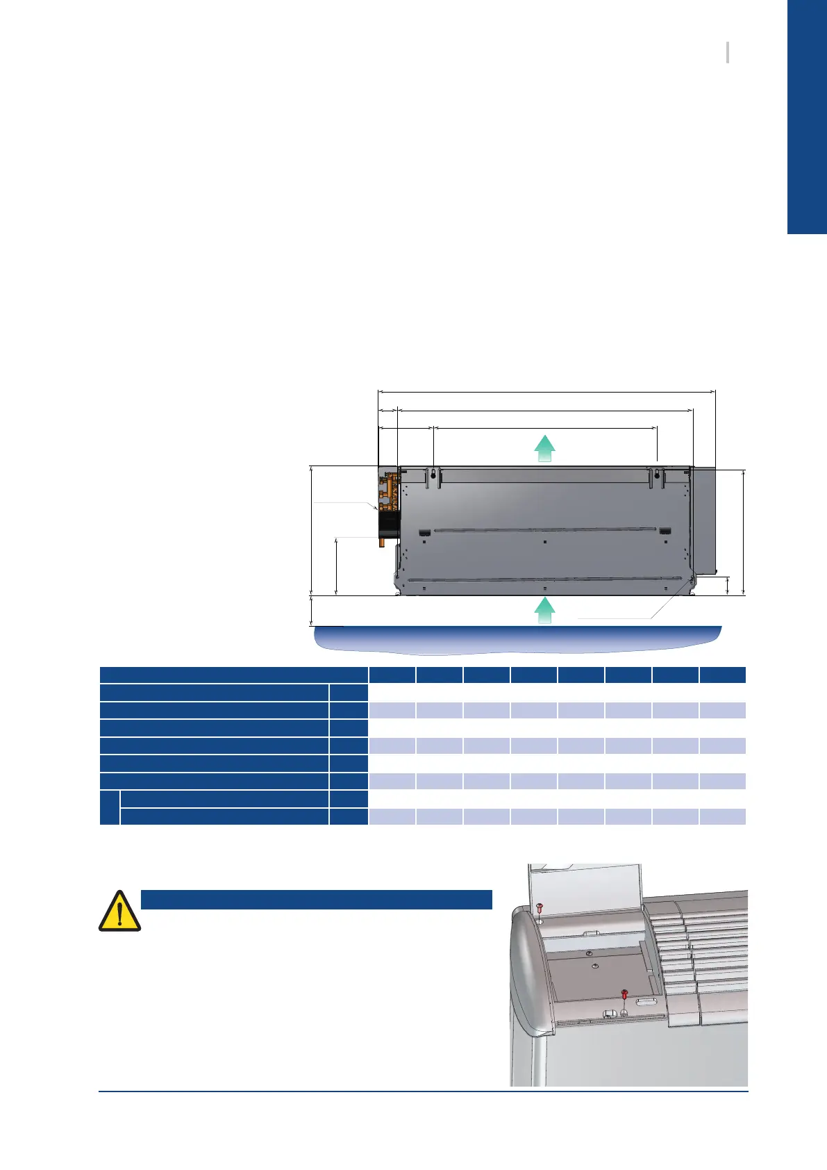
When removing cabinet do not pull or lift it up by the
discharge grilles, to avoid any damages on articulated
fasteners of the access doors.
Caution
100
192
430
E
F
DC
B
A
Return
Discharge
condensate
drain pan
M8 fixing screws
4 x 8mm
7SYSCOIL COMFORT
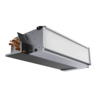
7.3.2. HN / HC CEILING UNIT
The HN / HC units are designed for ceiling mounting. Recommended xing by M8 threaded rod or 8 mm
diameter anchor bolts (contractor supply).
When the HN units are ducted at the inlet side, the controller return sensor must be located outside the fan
compartment in order to ensure its good operation.
For the HC model with cabinet, it is necessary to remove the cabinet before installing it.
Follow instructions for cabinet removal.
Drill holes in the ceiling in accordance with dimensions mentioned. Install the xing screws (contractor
supply).
Place the chassis unit on the xing points and screw it directly to the ceiling, or to the veritable support.
The fan coil unit should be pitched towards the drain side, to facilitate condensate evacuation.
On units with front air intake,
dimension 100 is not required.
Recommended xing by
M8 threaded rod with H8
hexagonal nut or 8 mm
diameter anchor.
On the VC and HC models, to hang the unit to the wall, it is
necessary to remove the cabinet.
To achieve this:
1. Remove the fastener screws from the access hatch situated
at the end of the unit, on the electrical connections side.
Size SCC10 SCC20 SCC30 SCC40 SCC50 SCC60 SCC70 SCC80
A mm
66.5 66.5 64 64 63 63 63 69
B mm
428 428 613 798 983 1 168 983 1 168
C mm
185.5 185.5 184 184 183 183 195 195
D mm
189 189 374 559 744 929 744 929
E mm
415.5 415.5 415.5 415.5 415.5 415.5 519 519
F mm
61 61 61 61 61 61 88 86
G
without auxiliary drain guard mm
569.5 569.5 753 938 1 122 1 307 1 121 1 316
with auxiliary drain guard mm
692.5 692.5 876 1 061 1 245 1 430 1 244 1 439
7.3.3. FIXINGS DIMENSIONS
7.4. CABINET REMOVAL
 Loading...