English
The unit base shall be arranged as indicated in the manual. There could be a risk of personal injury
or damage to property in the event of the unit being incorrectly supported.
Caution
400
400
100
400
100
6 SYSCOIL COMFORT
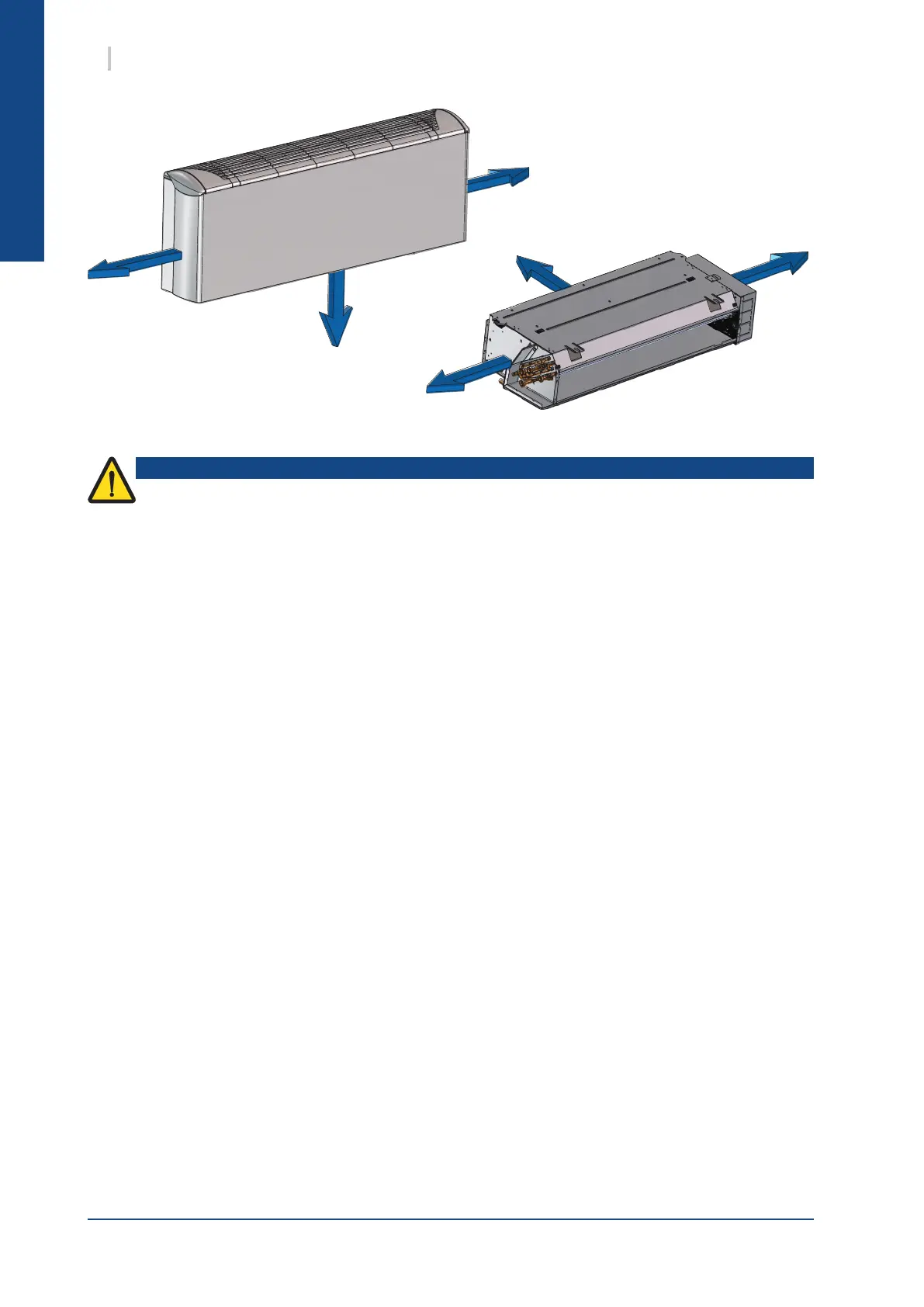
7.1. CLEARANCE
The unit must be installed on a rm level foundation, of adequate strength to support its full operating
weight.
1. It must be high enough to permit good drainage of defrost water with siphon
2. Keep duct connections to a minimum to reduce duct losses.
3. The unit must be pitched slightly towards condensate drain outlet to provide positive drainage of
condensates.
4. All electrical and ductwork connections to the unit must be made via exible connections to prevent
transmission of vibration.
5. In addition to the service clearances noted on the dimension sheet it is essential that provision is
made for adequate and safe service access.
7.2. UNIT LOCATION
Fan coil units are designed to be installed in a controlled environment. Each unit should be located on the
installation plans. Inspect the carton for specic tagging numbers and references. The supply, return and
condensation piping should be located accordingly making sure the piping will t into the connes of the
fan coil chassis and cabinet.
7.3. UNIT INSTALLATION
7.3.1. VN / VC CONSOLE UNIT
All units are to be installed against a wall as a oor console with support feet, or wall mounting as per
dimensional data. On the fan coil units equipped with support feet, we recommend you to x the unit to the
wall through the both oblong holes located on the upper part of the unit chassis.
On the VC model, to hang the unit to the wall, it is necessary to remove the cabinet.
Drill holes on the wall in accordance to the dimensions mentioned. Install the xing screws (contractor
supply).
Place the chassis unit over the xing screws through the oblong holes and screw it directly to the wall.
Ensure adequate space for pipings and electrical connection, and check side of connection.
 Loading...