6
| Installation
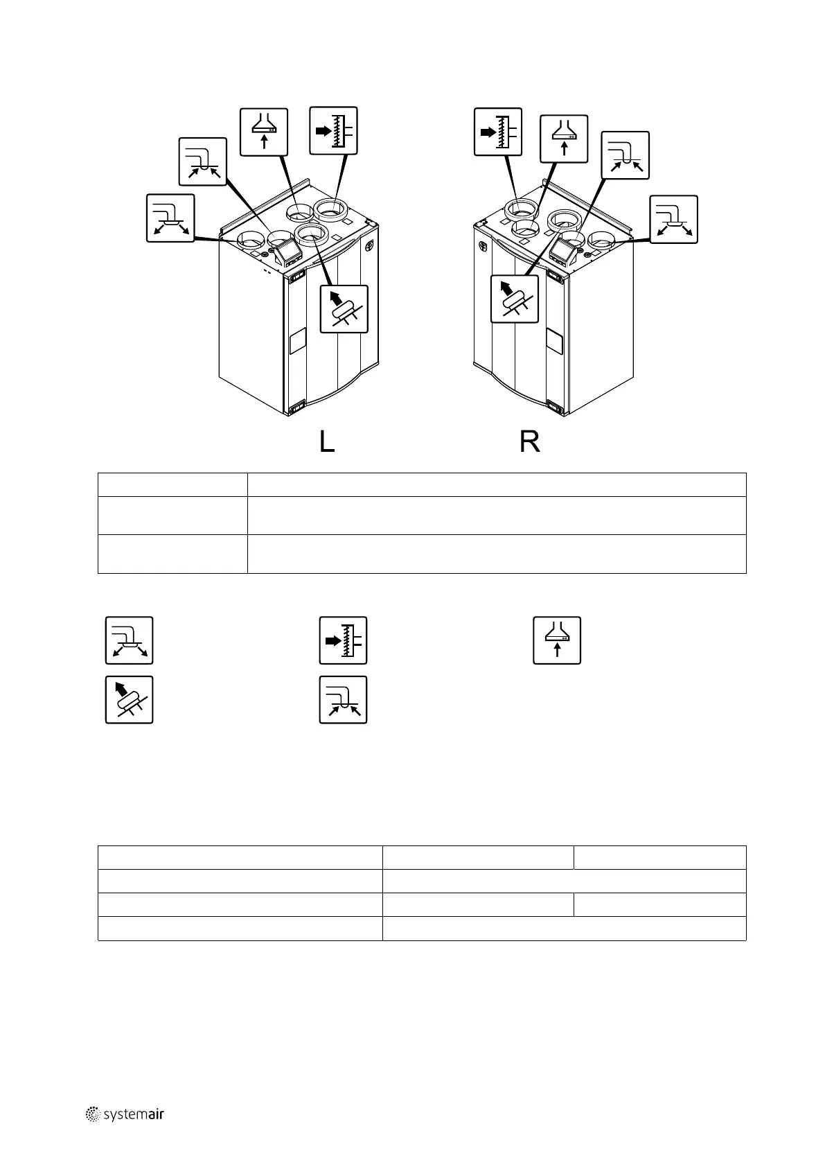
5.4.3 Connections Left and Right models
Position Description
R
Right hand model (Supply air connection is situated on the right hand side of the unit
viewed from the front)
L
Left hand model (Supply air connection panel is situated on the left hand side of the unit
viewed from the front)
Symbol
Description
Symbol
Description
Symbol
Description
Supply air
Outdoor air Cooker hood air
Exhaust air
Extract air
5.4.4 Power consumption and fuse size
SAVE VTR 250/B come with 500 W or 1000 W installed re-heater battery.
Table 1 Electrical data
Re-heater (W)
500 W 1000 W
Fans (W)
172 W
Total power consumption (W)
672 W 1172 W
Fuse (A)
10 A
6 Installation
This section describes how to install the unit correctly. To ensure a proper and fail-free operation, it is important that
the unit is installed according to these instructions.
211473 | A001

 Loading...