40
|
Accessories
3. Go to Components menu, select Extra Controller menu and select mode as Preheater. Pre-heater setpoint
can be set in the same menu. Do other advanced settings if necessary.
4. Configure connection of the pre-heater. Go to Service menu. Select Output menu. In next menu select DIGITAL
tab. Select the digital output to which the pre-heater connected. Example if it is connected to DO3 on the connection
board, then select DIGITAL OUTPUT 3 and select Step Controller Y4 Extra Controller from the output type
list.
5. Configure extra controller temperature sensor. Go back to Input menu. Select ANALOG tab. Select the analog input
to which the extra controller temperature sensor is connected. Example if it is connected to AI6 on the connection
board, then select ANALOG INPUT 6 and select Extra Controller Temperature Sensor (ECT) from the input
type list.
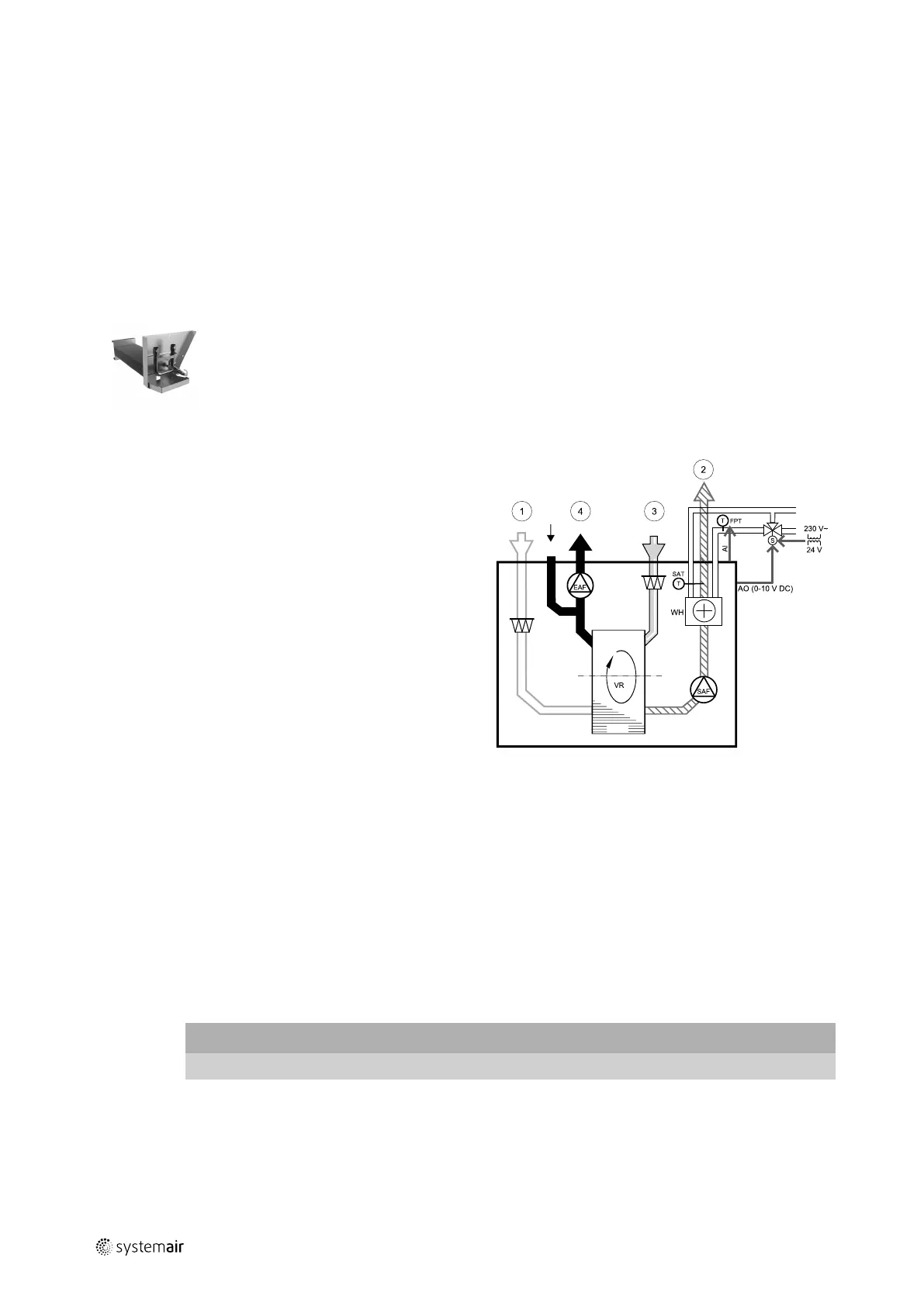
12.3.2 Internal water heater
A water heating battery can be installed inside the unit and connected to water system.
• WH — water heating battery
• FPT — frost protection sensor
• SAT — supply air temperature sensor
• S — actuator for valve
• 1 — Outdoor air
• 2 — Supply air
• 3 — Extract air
• 4 — Exhaust air
Component/product — Article number:
• Water battery VTR 250 — 211622
• RVAZ4 24A Actuator 0-10V (S) — 9862
• ZTV 15-0,4 2-way valve — 9829
• ZTV 15-0,6 2-way valve — 6571
• ZTR 15-0,4 valve 3-way — 9670
• ZTR 15-0,6 valve 3-way — 6573
Installation and connection
1. Remove plug and add the frost protection sensor. Tread seal the sensor.
2. Install water heater in the unit. Connect pipes, 2/3–way valve and actuator.
Important
Do NOT use 24V DC power output from the connection board for valve actuator.
3. Connect actuator (S) to any free analog output.
211473 | A001

 Loading...