Electrical connections |
27
• Alarms— detailed description of all alarms.
• Troubleshooting— information about all different possible malfunctions.
8 Electrical connections
The SAVE VTR 250/B is wired internally from factory.
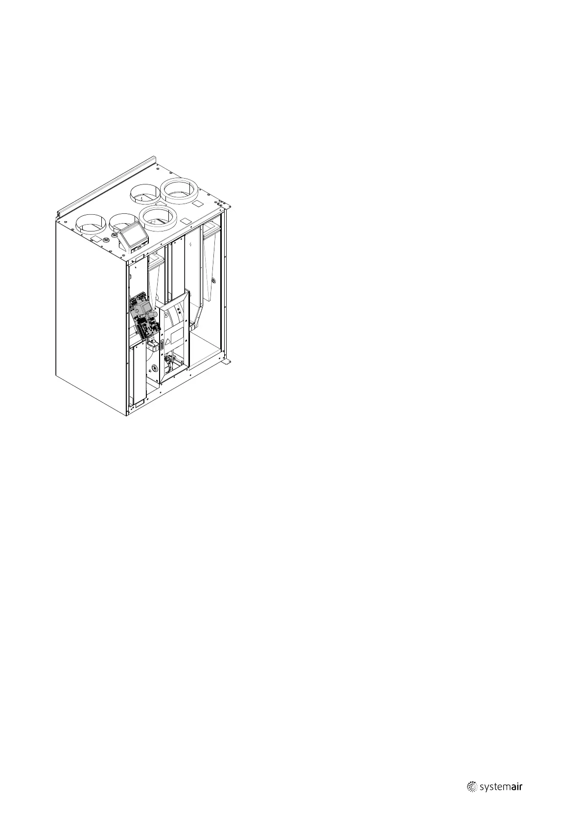
The electrical connection box can be found on the supply air outlet side of the unit. The print card can easily be taken
out from the unit, without using tools.
Fig. 6 Print card position
8.1 Main board layout
The SAVE VTR 250/B is equipped with built-in regulation and internal wiring.
The figure shows the main circuit board. See wiring diagram for more information.
211473 | A001

 Loading...