Accessories
|
47
8.5.3 Pressure Guard
A differential pressure switch is used to detect air pressure difference in a duct. The contact in the switch changes (on/
off) when air pressure exceeds the setpoint value.
One of the possibilities is to use this device with a cooker hood which has an internal fan. Turned on cooker hood causes
air pressure to increase in the exhaust air duct. After exceeding a set air pressure value in the pressure switch, wires
from the ventilation unit get connected by contact and signal is sent to the ventilation unit to activate the Pressure
Guard function.
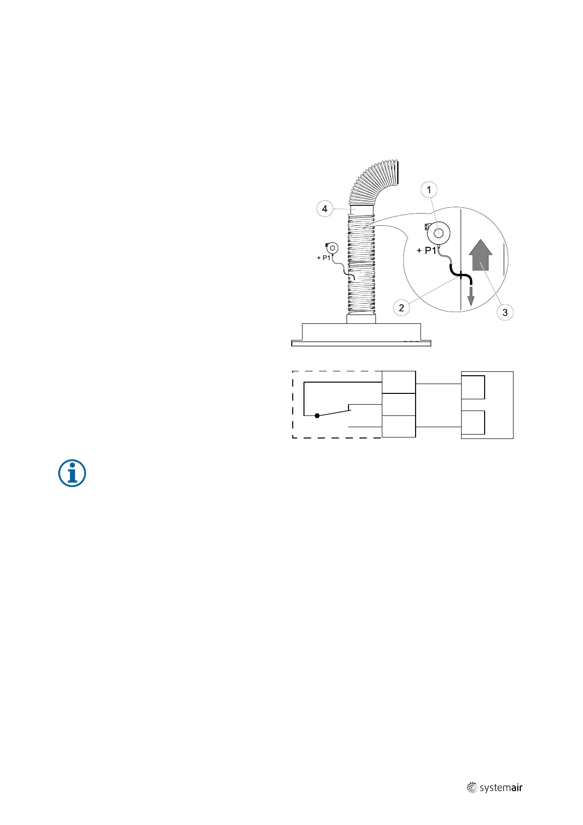
1 Mount a differential pressure switch.
Set the pressure switch to the lowest possible
pressure.
1. A differential pressure switch
2. Metal tube
3. Exhaust air direction
4. Exhaust air duct
2 Install a rubber bush in the duct. Insert the S-shaped
copper pipe into the rubber bushing so that it points
towards the air flow (i.e. towards the outlet opening
for the fan).
3 Connect plastic tube to P1 positive pressure connec-
tion (P2 negative pressure connection shall be left
open), the other end of plastic tube should be con-
nected to the copper pipe installed in the duct.
4 Connect wires from the connection box (UI, 24V) to
the pressure switch (common, normally open).
Please contact your installer to find air pressure for
your system. It may necessary to perform several
tests and calibrations to find pressure, increased by
the cooker hood, at which the differential pressure
switch gets activated.
Note:
Connection with a minus sign (P2) on the pressure switch must be open, remove a plastic cap if it is present.
The exhaust air pressure and air pressure increase caused by the cooker hood is different for each
ventilation system.
Set the switch activation pressure value using the knob under the lid. The setpoint value is visible through
the lid.
Configuration
1. Go to Service menu
2. Enter password (default 1111)
3. Go to Input menu. Select UNIVERSAL tab.
4. Select the universal input to which wire from the differential pressure switch is connected.
Example if it is connected to UI1 on the connection board, then select option UNIVERSAL INPUT 1. Set signal type as
Digital Input and select an option Pressure Guard from the input type list.
8.5.4 Multiple control panels
Multiple control panels (up to 10) can be connected to one unit with the help of diverting plugs. A single diverting plug
allows to connect two control panels. A diverting plug can be connected to another diverting plug to further increase
the number of control panels that can be connected simultaneously.
UI
24 V
CB
COM
NC
NO
| Rev01

 Loading...