18
Antifreeze
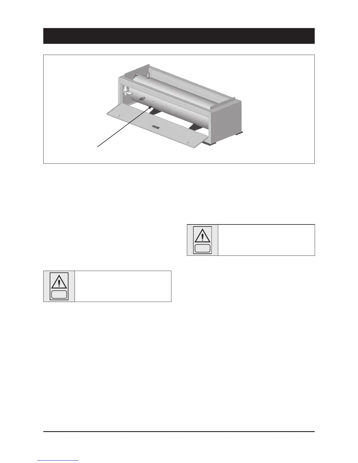
Resistance Wiring
4 - Installation
4.7 Electrical connections
The unit must be installed on site according to the usual
procedures and standards applicable in the place of
installation. The unit must not be operated if its installation
has not been carried out according to the instructions
provided in this manual.
The power supply lines must consist of insulated copper
conductors, dimensioned for the maximum absorbed
current.
Connection to terminals must be performed according to the diagram
of connections (User’s Terminal Box) provided in this manual and
according to the wiring diagram which accompanies the unit.
WARNING
Before connecting the power supply lines, check
that the available voltage value does not exceed
the range specified in the Electric Data (Chapter
9).
For 3-phase systems, check also that the unbalance between the
phases does not exceed 2%. To perform this check, measure the
differences between the voltage of each phase couple and their mean
value during operation. The maximum % value of these differences
(unbalance) must not exceed 2% of the mean voltage.
If the unbalance is unacceptable, contact the Energy Distributor to
solve this problem.
WARNING
Supplying the unit through a line whose
unbalance exceeds the permissible value will
automatically void the warranty.