22
6 - Control (continued)
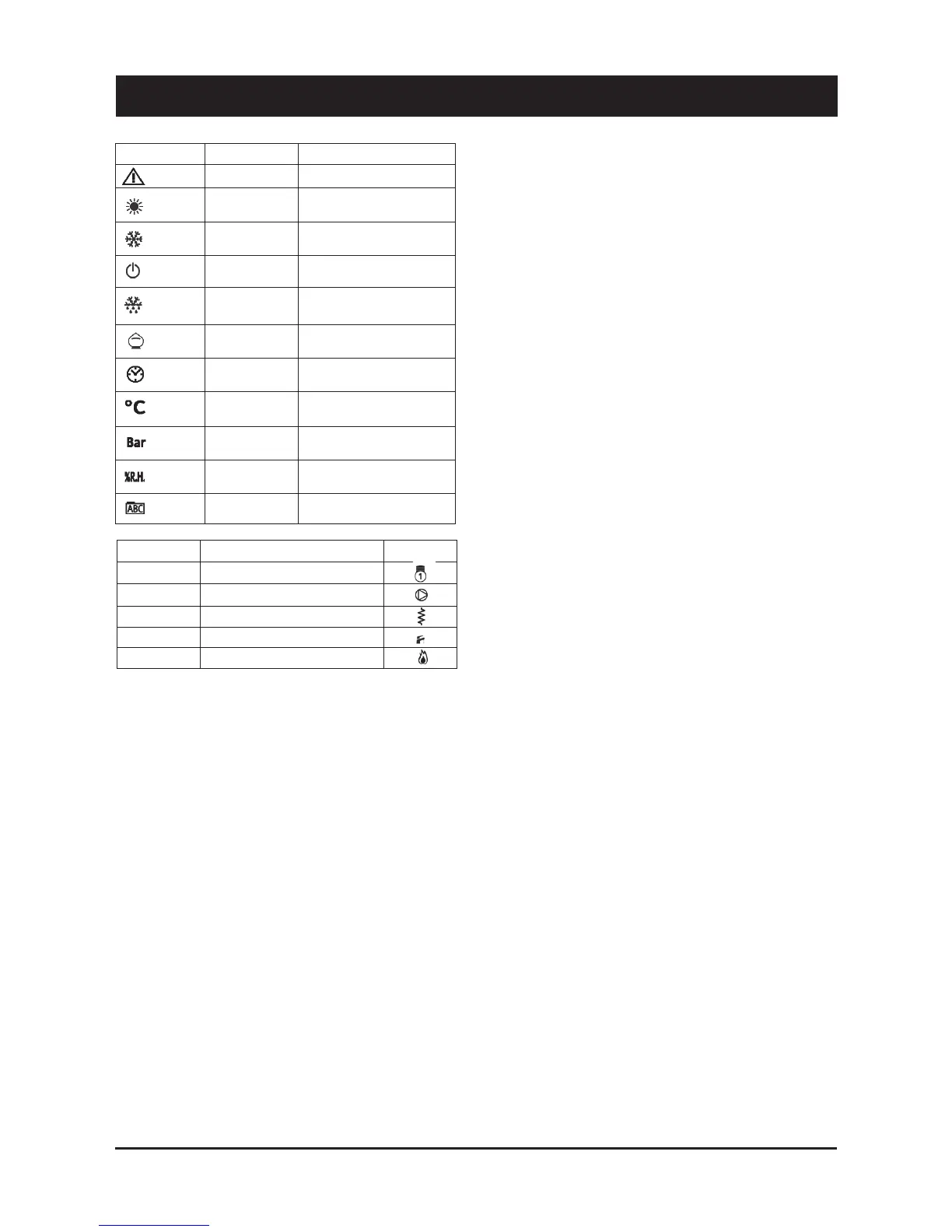
ICON / COLOR STEADY ICON BLINKING ICON
- Alarm ON/ RED
/ GREEN
/ GREEN
/ GREEN
/ GREEN
/ GREEN
/ RED
/ RED
/ RED
/ RED
/ RED
- Mode: HEATING
- Current HR
- Time slots activ.
- Mode: COOLING
/
/
/
- Mode: STAND-BY
- Configurable
Not used
Menu surf
- Alarm QUIT
- Antifreeze+Heat pump ON
- Heating mode by remote
- HR setting
- Time slots programming
- Cooling mode by remote
/
/
/
- Stand-by mode by remote
- Configurable
Not used
/
6.3 Folder structure
Folder structure is composed of totally four menus
1) Main display"#"used to set what to display without acting on any
key
– Ai"#"analogue input (temperature, pressure)
– rtC"#"room time clock
– SetP"#"standard set-point
– SetR"#"corrected set-point (according to climatic correction,
etc.)
2) Operating mode"#"used to set operating mode
– StbY"#"stand-by
– HEAT"#"heating
– COOL"#"cooling
– AS"#"sanitary hot water
3) Status"#"used to show resources values
– Ai (AIL/AIE/Air)"#"analogue inputs (main board / expansion
board / remote terminal)
– di (diL/diE)"#"digital inputs (main board / expansion board)
– AO (AOL/AOE)" #" analogue outputs (main board/expansion
board)
– CL (HOUr/dAtE/YEAr)"#"clock
– AL (Er00"#"Er98)"#"alarms
– SP"#"standard set-point
– Sr" #" corrected set-point (according to climatic correction,
etc.)
4) Program"#"define parameters, functions, password and to display
alarm log
6.4 Menu structure
“Program” menu is composed of totally four folders
1) Parameters"#"change unit parameters
2) Functions"#"manual operations (switch ON / switch OFF, alarm
quit, historic alarm delete, multi function key use)
3) Password"#"define visibility levels for parameters/folders
4) Alarm log"#"display alarm log
Parameter folder gives access to following sub-folders
– CL/CE/Cr/CF"#"configure device I/O (L"#"local; E"#"expansion; r "
#"remote; F"#"serial)
!" #$#%&'()" *$+(,-" .,/+)" &0" +1&2)3" 1#$')3" 4*00)1)$,*#%3" %&'*5"
function)
!" 4*'*,#%"*$+(,-".%&'*5"0($5,*&$6
!"" 4*'*,#%"&(,+(,-".%&'*5"0($5,*&$6" "
!"" #$#%&'()"&(,+(,-".1#$')6
!"" -)1*#%"5&$0*'(1#,*&$".5&77($*5#,*&$"+#1#7),)1-6"
– TR"#"define thermoregulation parameters
!"" -),8+&*$,".7#9:7*$:;/-,)1)-*-6" "
!"" ,/+)".+1&+&1,*&$#%:4*00)1)$,*#%6" "
!"" +1&2)"-)%)5,*&$"" "
– ST"#"define operating status
!"" 5&&%*$'"&$%/" "
!"" ;)#,*$'"&$%/" "
!"" -5&&%*$'"#$4";)#,*$'""" "
!"" 5;#$')8&<)1""
– CP"#"configure compressor parameters (type/number/timing)
– PI"#"define primary circuit / source side circuit pump parameters
/ functions
!"" &+)1#,*$'"7&4)".4*-#2%)":"#%=#/-">?":">?"*0"5&7+1)--&1">?6
!"" 4*'*,#%":"#$#%&'()"5&$,1&%" "
!"" #$,*8-,*5@*$'" "
!"" #$,*801))A)" "
– BR "#" control the parameters for an additional step for heating
and for sanitary hot water integration (boiler)
!"" &+)1#,*$'"7&4)".4*-#2%)":"4*00)1)$,*#%""#" fixed or in function of
outdoor air temperature)
!"" -),8+&*$,":";/-,)1)-*-" "
– DS"#"define set-point offset (dynamic set-point) depending on
!"" #$#%&'()"*$+(,".BCDE3"BCFE3"BCDBE3"GCHB7I6"
!"" &(,4&&1"#*1",)7+)1#,(1)""
!"" 1&&7",)7+)1#,(1)" "
– AD"#"simulate an electronic inertial accumulator, acting on set-
point and hysteresis (adaptive function), by confronting minimum
/ effective ON-OFF time
– AS"#"define sanitary hot water management parameters
!"" &+)1#,*$'"7&4)".4*-#2%)":"-#$*,#1/";&,"=#,)1"<#%<)":"1)-*-,#$5)"
/ pump)
!"" -),8+&*$,":";/-,)1)-*-" "
!"" #$,*8%)'*&$)%%#"0($5,*&$" "
– HP"#"define heat pump block management parameters
!"" &(,4&&1"#*1",)7+)1#,(1)""
!"" ,;)17&1)'(%#,*&$",)7+)1#,(1)" "
!"" 4*'*,#%"*$+(," "
– PL" #" define capacity limitation to protect the unit (high/low T,
high/low P)
– TE" #" define time slots management (different operating daily
profiles)
– AL"#"define alarms management (automatic / manual reset, by-
pass time, sampling)
LED N°* DESCRIPTION ICON
First capacity step
Primary circuit pump
Electrical heater
Sanitary hot water valve / pump
Boiler
1
3
5
6
7