42
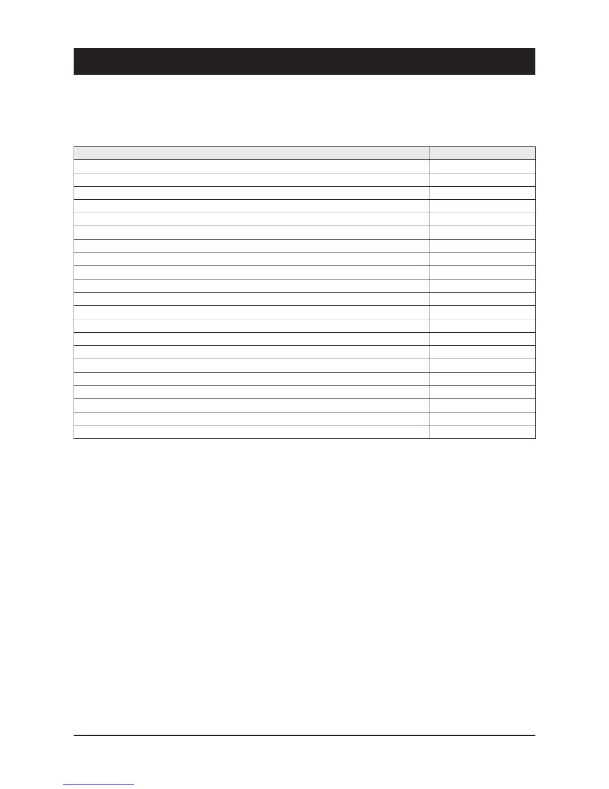
11.1 Spare part list
The table below shows the list of spare parts recommended during
the first two years of operation.
11.2 Oil for compressors
The compressors are lubricated with polyester oil (P.O.E.).
11.3 Wiring diagrams
The wiring diagrams are installed inside the doors of the electrical
panels of the unit. Any request for wiring diagrams shall be forwarded
to manufacturer’s Service Centre.
Component Number
Fan 1
High pressure switch 2
Differential water pressure switch 1
High pressure transducer 2
Low pressure transducer 2
Expansion valve 1
Gas filter 1
Four-way valve 1
Electronic main board 1
Auxiliary main board transformer 1
Auxiliary circuit transformer 1
Compressor contactor 2
Pump contactor 1
Water sensor 4
Air sensor 1
Automatic switch compressor protection 2
Automatic switch pump protection 1
Auxiliary contact 4
Fan capacitor 1
Auxiliary switch 1
Fuses 4
11 - Spare Parts