Topvex FR800, FR1600, FR3800 Operation and Maintenance Instructions
Systemair Inc.
5
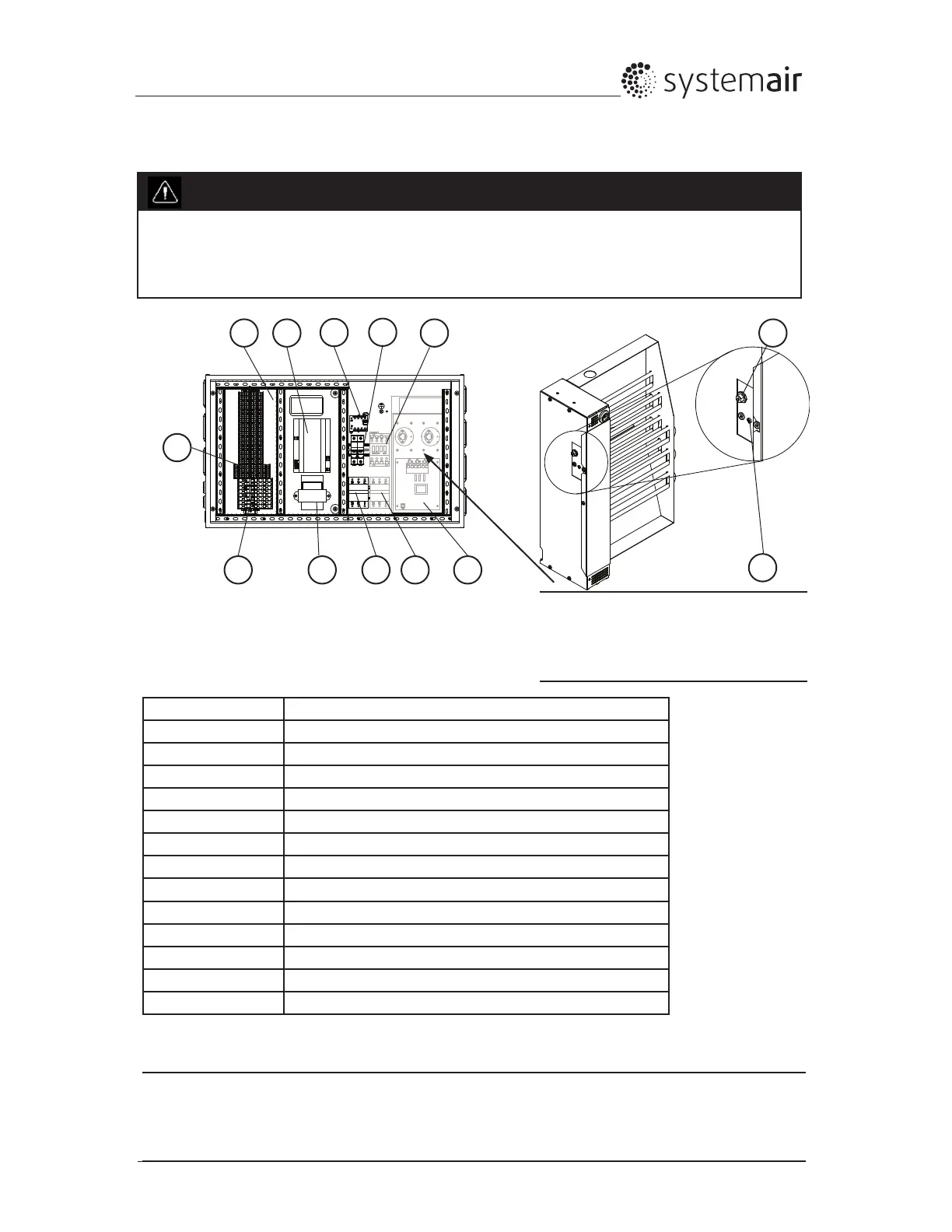
2.3 Internal components Electrical connection box
Danger
• Make sure that the Main power supply to the unit is disconnected before performing any
maintenance or electrical work!
• All electrical connections must be carried out by an authorized installer and in accordance with local
rules and regulations.
Fig. 3 Electrical components
Table 2: Description of electrical components
Note:
Electric heater section. (Present in EL units
only)
Position Description
1 Controller E-28 (UC)
2 Transformer208-230/24VAC(TR24)
3 Terminals for internal and external components (TB3)
4 Terminals for internal wiring (TB2)
5 Terminals for main power voltage to the unit (TB1)
6 Contactor (K1) On/Off rotor motor
7 Contactor (K3) On/Off control of EL heater (EL units only)
8 Automatic fuse (AS1)
9 Automatic fuse for heater (AS2) (EL units only)
10 Automatic over heat protection reset (EL units only) (OT1)
11 Manual over heat protection reset (EL units only) (ET1)
12 TTC EI heater control
13 Fuse holders F1 and F2
Note:
Forpre-heatercomponents,pleaserefertothe“HWC-EPHInstallationInstructions”manual(420353).
1
9825
4
3 7
6
11
10
12
13

 Loading...