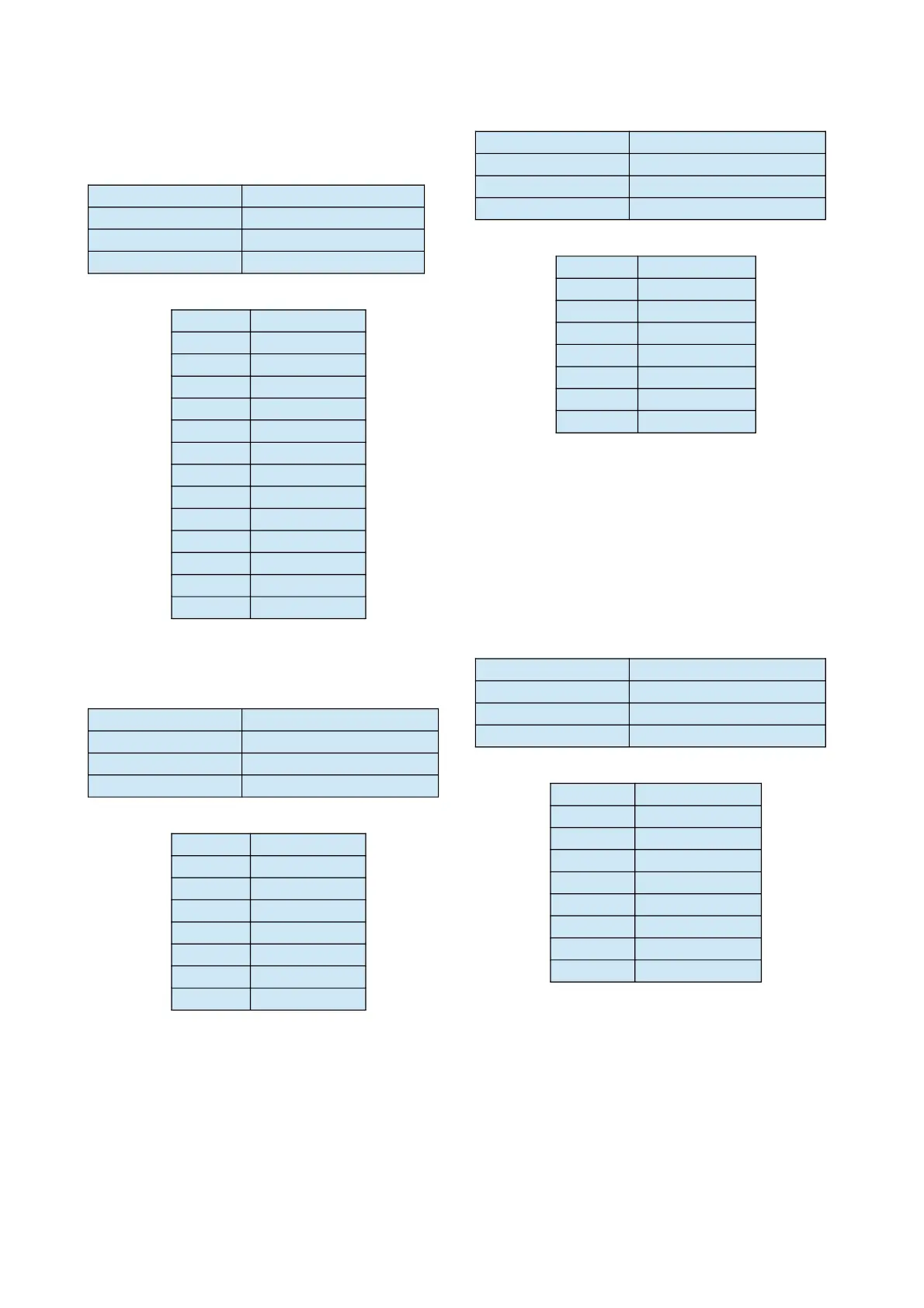
X.21 Port
The electrical characteristics and the pin out of the
connector is detailed below:-
X.21 Type Fixed DTE
X.21 Speed 64Kbps to 384Kbps
X.21 Signals C, I, TXD, RXD, CLK
X.21 Connector 15-way Dsub Female
PIN SIGNAL
1 Protect GND
2 T(a)
3 C(a)
4 R(a)
5 I(a)
6 S(a)
7 N/C
8 Signal GND
9 T(b)
10 C(b)
11 R(b)
12 I(b)
13 S(b)
INSTALLATION NOTE: The user is advised to ensure the
DCE connector of the X.21 cable is terminated correctly.
Manager Input Port
Type V.24/RS232 - Fixed DCE
Speed 9600bps (8,n,1)
Signals TXD, RXD, SIG GND
Connector 9-way Dsub Female
PIN SIGNAL
2 RXD (o/p)
3 TXD (i/p)
5 SIG GND
6 Relay 1 COM
7 Relay 1 N/O
8 GND
9 Opto 1 (i/p)
* Opto Input – Trigger by strapping to ground.
Manager Output Port
Type V.24/RS232 - Fixed DTE
Speed 9600bps (8,n,1)
Signals TXD, RXD, SIG GND
Connector 9-way Dsub Female
PIN SIGNAL
2 RXD (i/p)
3 TXD (o/p)
5 SIG GND
6 Relay 2 COM
7 Relay 2 N/O
8 GND
9 Opto 2 (i/p)
* Opto Input – Trigger by strapping to ground.
Auxiliary Data Port
The RS232 terminal interface can support auxiliary
bidirectional transmission of asynchronous data
over the ISDN and X21 network.
Type V.24/RS232 - Fixed DCE
Speed 9600bps (8,n,1)
Signals TXD, RXD, CTS, S GND
Connector 9-way Dsub Female
PIN SIGNAL
1 Alarm N/C
2 AUX RXD (o/p)
3 AUX TXD (i/p)
4 Alarm COM
5 SIG GND
6 Alarm N/O
8 AUX CTS (o/p)
9 Remote Trigger*
NOTE: The CTS output signal should be used for Flow
Control when Auxiliary Data is enabled.
Page 24