User Manual 9250
Portrayal 2-7
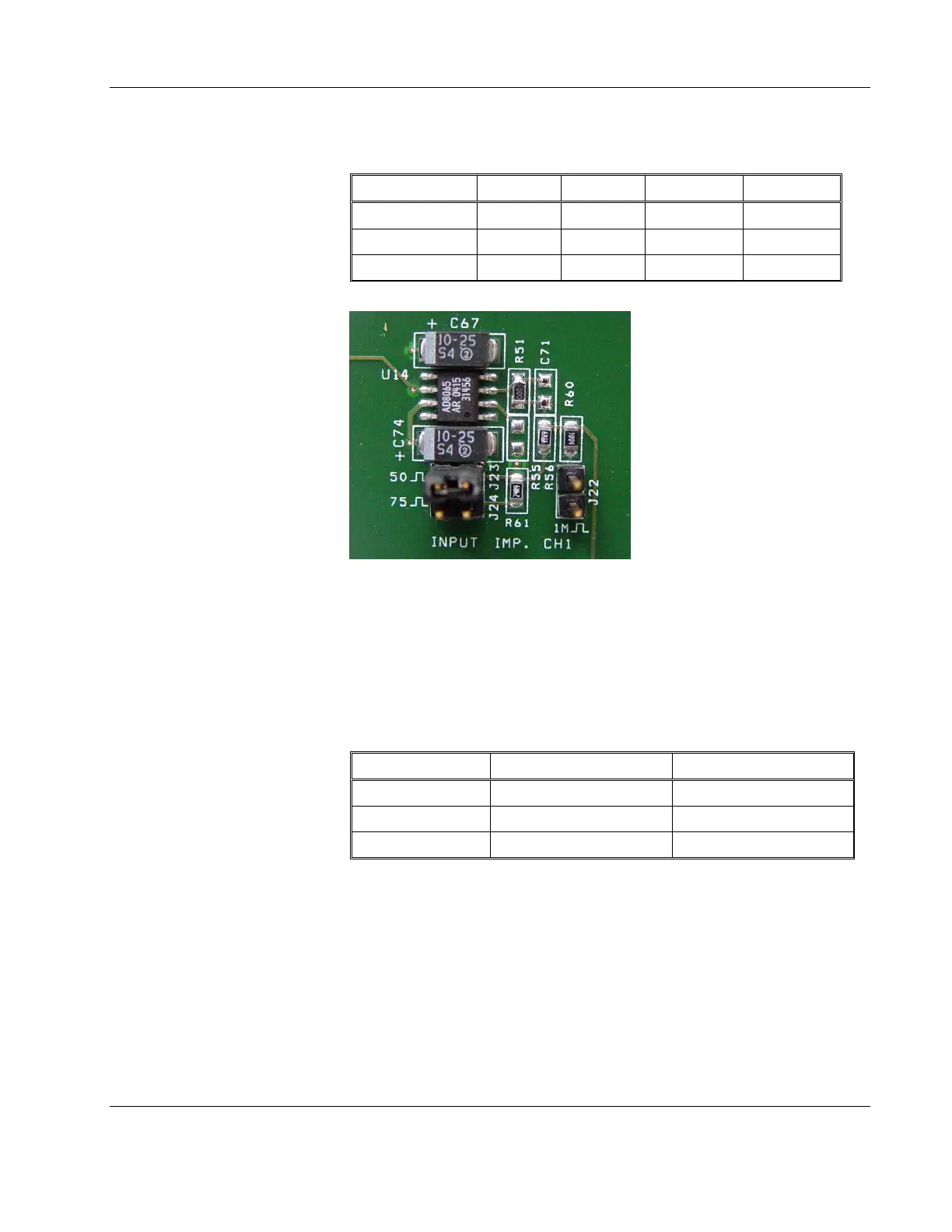
Table
2-1, Input Impedance Jumpers
Impedance CH1 CH2 Aux CH1 Aux CH2
50Ω J23 J5 J29 J14
75Ω J24 J11 J28 J13
1MΩ J22 J6 J30 J15
Figure 2-1, Field Modification of Channel 1 Input Impedance
Configure the Source (Output) Impedance
Before you change the 9250 source (output) impedance settings,
identify first the jumper location for all of the Outputs. Place the
jumpers as required according to the table 2-2.
Table
2-2, Output Impedance Jumpers
Impedance CH1 CH2
50Ω J20 J9
75Ω J21 2-3 J10 2-3
600Ω J21 1-2 J10 1-2
Configure Input/Output Coupling
The default input/output coupling is DC. Before you change the 9250
input/output coupling settings, identify first the jumper location for all
of the inputs and outputs. When the jumpers are on the links, the path
is DC coupled. Remove the jumpers from the link to modify the
settings to AC. Place or remove the jumpers as required according to
table 2-3 and 2-4.