User Manual 9250
Portrayal 3-7
Output Distortion
Equipment: Distortion Analyzer, Function Generator
Preparation:
24. Connect the 9250 Channel 1/2 outputs to the distortion ana-
lyzer input. Use 50Ω feedthrough termination at the distortion
analyzer input
25. Configure the function generator as follows:
26. Function: Sine wave
27. Frequency: 10Hz
28. Amplitude: 1Vp-p
29. Connect the function generator to the 9250 channel 1/2 input
Test Procedure
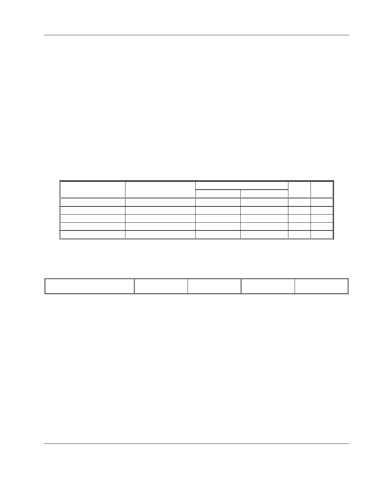
1. Perform distortion tests on both channels using Table 3-3
Table 3-3, Output Distortion Tests
Function Generator Distortion Reading
Frequency Setting Reading Limits CH 1 Output CH 2 Output Pass Fail
10.00Hz < 0.1%
100.0Hz < 0.1%
1.000kHz < 0.1%
10.00kHz < 0.1%
100.00kHz < 0.1%
2. Remove the cables from the front panel inputs repeat the tests
using the rear panel inputs
Test Results
Pass Fail
Output Spectral
Purity
Equipment: Spectrum Analyzer, Function Generator
Preparation:
30. Connect the 9250 Channel 1/2 outputs to the spectrum ana-
lyzer input. Use 20dB feedthrough, 50Ω attenuator at the
spectrum analyzer input
31. Configure the function generator as follows:
32. Function: Sine wave
33. Frequency: 1MHz
34. Amplitude: 1Vp-p
35. Connect the function generator to the 9250 channel 1/2 input
Test Procedure
1. Perform signal purity tests on both channels using Table 3-4