User Manual 9250
2-8 Portrayal
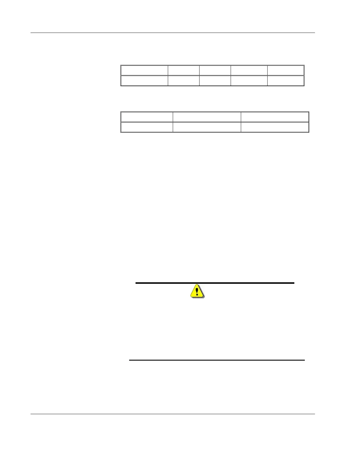
Table
2-3, Input coupling Jumpers
Input CH1 CH2 Aux CH1 Aux CH2
Link J27 J4 J31 J16
Table
2-4 , Output coupling Jumpers
Impedance CH1 CH2
Link J19 J8
Configure Single-ended or Differential Outputs
The default configuration is single-ended. If you order the amplifie
with differential outputs, channel 2 input is disabled and channel 1
output is amplified and routed differentially to both channels 1 and 2.
Channel 1 outputs the normal signal and channel 2 outputs the
inverted phase signal.
The rear panel, as shown in Figure 1-2 has a push-push switch.
Pressing the switch once, will activate the differential mode and will
cause a light on the rear panel to illuminate. Pressing the switch again
will disable the differential mode and allow each amplifier to operate
separately.
The differential source impedance must be adjusted in the factory to
your requirement. For true differential source impedance, the output
source impedance is halved. For example, instead of 600Ω, each
channel has 300Ω however, since each channel is inverted 180° to
the other channel, the source impedance is summed and presents
true 600Ω to the load.
WARNING
Output impedance for differential mode is factory set for
differential drive. If you change the rear panel switch set-
ting to Differential OFF position, the source impedance
is half of what should be for normal operation. Changing
from differential mode to normal must without changing
the internal source resistors will double the output am-
plitude and may damage your equipment.