Do you have a question about the Tadano GR-130EX and is the answer not in the manual?
Specifies applicable model numbers and serial number ranges for this service manual.
Lists related service manuals required for comprehensive repair and maintenance procedures.
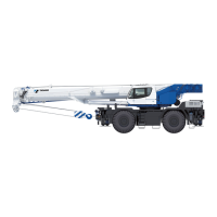
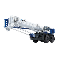
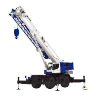
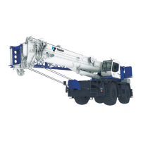
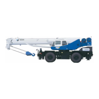
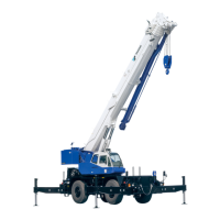
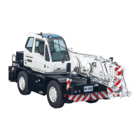
Illustrates the external components of the rough terrain crane in its traveling posture.
Outlines the technical specifications and features of the GR-130E-2 model, including boom sections and engine.
Provides conversion factors for various units of measurement like length, speed, area, volume, and force.
Groups tables for mass, pressure, torque, power, and temperature conversions.
Explains the third angle projection method used for mechanical drawings and illustration types.
Lists the main chapters and sections of the service manual, categorized into 'Data, Adjustment and Checks' and 'System Diagrams'.
Provides core service data including oil/coolant capacities, operating speeds, and mass table.
Details procedures for adjusting hydraulic pressure for various crane functions like winches and elevating.
Outlines procedures for adjusting pneumatic pressure for brake systems and other pneumatic controls.
Explains the steps for bleeding air from hydraulic pumps, brakes, and motors to ensure proper function.
Details electrical adjustments for switches related to boom retraction, jib lock, and drum rotation.
Covers the adjustment of boom telescoping wire ropes and related components for proper crane operation.
Details adjustments for traveling components like service brakes, accelerator, and steering angle.
Outlines checks for outrigger status, hoisting, jib functions, and boom telescoping control.
Details checks for exhaust brake, automatic transmission, rear steering lock, and suspension lock.
Provides a maintenance table with inspection intervals for various circuits and components.
Lists specifications for boom connecting pins and their thread sizes.
Provides comparison table and diagram for hydraulic parts and circuits.
Details the torque converter circuit diagram, including components and their connections.
Presents the pneumatic circuit diagram, illustrating air brake and control systems.
Covers comparison table and diagrams for the upper electrical circuits, including inside cab components.
Provides comparison table and diagrams for the lower electrical circuits, including engine start and main circuits.
Illustrates the location of upper hydraulic parts for the unit, winch, telescoping, elevation, slewing, return, drain, steering, air conditioner, and operation valves.
Illustrates the lower hydraulic parts location for steering, suction, outrigger, and center joint.
Shows the location of hydraulic parts related to the torque converter assembly.
Illustrates the location of pneumatic components, including service brake and control parts.
Details the location of upper electric parts inside the cab, including relays, switches, and control units.
Shows the location of lower electric parts, including the main unit box, MDT, and fuse boxes.
Provides harness diagrams for upper components like main, horn, slewing table, boom, and AML systems.
Details harness diagrams for lower components such as air, electronic governor, and engine start systems.
Explains system configuration, circuit diagrams, and adjustment procedures for the view system (cameras/monitor).
| Brand | Tadano |
|---|---|
| Model | GR-130EX |
| Category | Construction Equipment |
| Language | English |