XT-3 Reader Installation Manual & Data Sheet Doc no. 11-267 02
© TagMaster NA 24 (28)
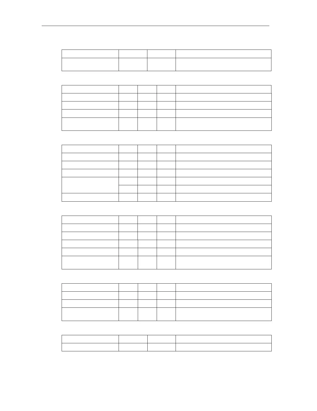
5.4.3 Serial interfaces RS232 and RS485, J41 – J43
Parameter Min Max Unit
Isolation to Shielding and
Chassis
1500 V
5.4.4 Isolated inputs, J51
Parameter Min Max Unit Measured between pins
High Voltage (active) 2.4 30 V 1-2, 3-4, 5-6
Low Voltage(inactive) 0 0.2 V 1-2, 3-4, 5-6
Input Impedance 1000 Ohm 1-2, 3-4, 5-6
Isolation to Shielding and
Chassis
1500 V 1…6 to chassis
5.4.5 Isolated outputs, J52
Parameter Min Max Unit Measured between pins
Applied Voltage Out 1,2 1 30 V 1-2, 4-5
Sink Current Out 1 0 500 mA 1-2
Sink Current Out 2 0 100 mA 4-5
12 30 V 3-2, 3-5
Supply
3 9 mA 3-2, 3-5
Isolation to Shielding 1500 V 1…5 to chassis
5.4.6 Relay, J1
Parameter Min Max Unit Measured between pins
Switch Current 2 A 1-2, 1-3
Switch Voltage DC 60 V 1-2, 1-3
Switch Voltage AC 30 Vrms 1-2, 1-3
Switch Power 50 W 1-2, 1-3
Isolation to Shielding and
Chassis
1500 V 1…3 to chassis
5.4.7 Wiegand/Mag-stripe, J2
Parameter Min Max Unit Measured between pins
Voltage 30 V 1-4, 2-4, 3-4
Sink Current 50 mA 1-4, 2-4, 3-4
Isolation to Shielding and
Chassis
1500 V 1…4 to chassis
5.4.8 USB, P2
Parameter Min Max Unit
Total Current Supply 500 mA