XT-3 Reader Installation Manual & Data Sheet Doc no. 11-267 02
© TagMaster NA 15 (28)
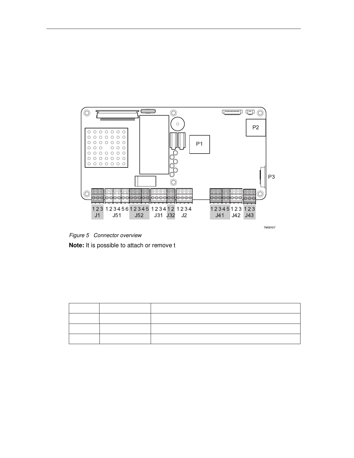
5.2 Interfaces
5.2.1 Connector Overview
For easy installation and service the cables are screwed into removable block
connectors.
TM00107
1 2 1 2
J1 J31 J32J51 J52
3 4 5 6 1 2 1 3 42
J2
1 3 421 23 4 5
J41
1 2 3 4 53 1 2
J42
P1
P2
P3
3 1 2
J43
3
Figure 5 Connector overview
Note: It is possible to attach or remove the terminal block connectors inside the reader
for more convenient connection of the cables.
The terminals are grouped as specified in the sections below.
5.2.2 Relay Output, Group J1
The controller board has one relay output.
Table 3 Relay Output, Group J1
Pin Signal Description
1 RCOM Common terminal
2 ROPEN Connected to RCOM when relay is open
3 RCLOSE Connected to RCOM when relay is closed
5.2.3 Wiegand/Mag-stripe, Group J2
The controller board has an access control interface that supports both Wiegand and
Mag-stripe protocols.