M850-00
T858/859 Circuit Operation
D2.3
Copyright TEL 31/09/98
2.1 Introduction
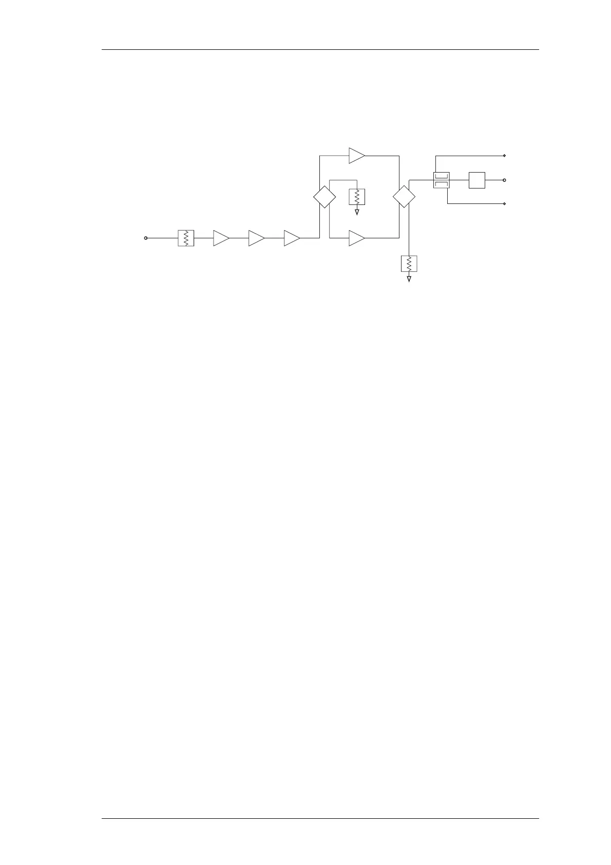
Figure 2.1 T858/859 High Level Block Diagram
The T858 and T859 comprise a five-stage RF power amplifier, the final two stages of
which are combined, and extensive control circuitry.
Figure 2.1 shows the configuration of each of the main circuit blocks on a functional
level, while the fold-outs Figure 1.1 and Figure 1.2 show their location on the PCB.
L19
L39
LPF
HPF
50
Load
Ω
50
Load
Ω
Q1 Q3
(T858 &
T859 Only)
Q4 Q7
Pad
RF In
Q6
0.7-1W
0.7-1W
0.7-1.8W
2-3dB
2dB
4dB
2W
5W
5W
8-10W
15-20W
20-30W
40-50W
20-35W
35-40W
60-70W
35-40W
60-70W
105-120W
60-80W
Forward
Power
RF Out
Reverse
Power
T858
T859
T878
 Loading...


