24
Installation
・ Connect the cable from the microscope unit to
the left of the sockets.
・ Connect the cable from the XY coupling unit to
the right of the sockets.
4. Attach the cover to its original location.
Fromthe
microscopeunit
OM8-T46
FromtheXY
couplingunit
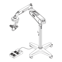
● Connecting the Foot Switch Unit
*Use the foot controller unit specified by our
company.
*Connect the foot controller to the arm unit
where patients are absent.
1.Connect the foot switch connecter to the foot
switch power socket of the arm unit.
2.Tighten the attaching screws.
Tightenthescrews
OM8-T47
OM8-T47-1
Removefourscrews
■ Changing the Pedal Layout of the Type I Foot Controller
● The pedal layout of the Type I foot controller
can be changed.
1. Remove four screws in the back of the foot
controller, then remove the back cover.
㪝
㪪
㪬
㪚
㪦
㪦
㪚
㪬
㪪
㪝
㪱
㪤
㪦
㪦
㪱
㪦
㪦
㪤
ZOOM
LO
ZOOM
HI
FOCUS
UP
FOCUS
DOWN
OM8-T47-2
*Original pedal layout and connections of each
connector are as the right illustrate.
 Loading...