fr,
I_
-
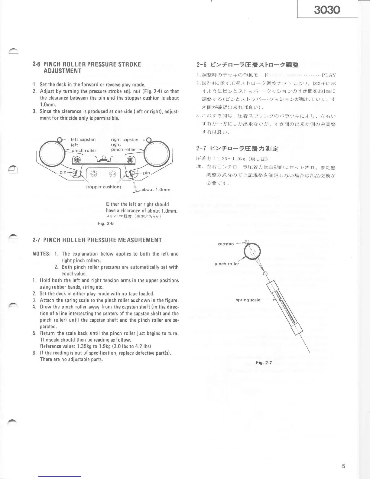
2.6 PINCH
ROLLER PRESSURE
STROKE
AOJUSTMENT
1.
Set
the deck
in the
fonrvard
or reverse
play
mode.
2. Adjust by turning
the
pressure
stroke
adj. nut
(Fig.24)
so
that
the clearance
between the
pin
and the
stopper cushion
is
about
1.0mm.
3.
Since
the clearance is
produced
at one
side
(left
or right),
adiust-
ment
f
or this
side only is
permissible.
2-
6
e
>
U
a
-
-
EEfi
71.
a
-
2##.
1,ffi45F+ot'y
*alFLlt=
F......--......'..
.PLAY
2.v12-41.^-{ta€z
F
t]
2iw*t'y
l-.
t.J
r],
E2-6t.7ji
t* )
l. t>
t
),
F'y
/\-.)'y
)= >atdffrti('tlnnl:
ffi#T
6
(E>
t z
F'y
/\-.
2'y
)t
=
>r\HEfi(t\<,
_f
-
ffi
,.rE-;U.,u
*ft
lt.C t\
)
.
3. a0')adf,El{t,
It
EAtt)
>t0))\-'y
+t-&
tJ
,
}-l'u.\
t
nh,
-t
t.
L
r\,lH*Ar\r\,
T3 F,i')fi.*hl$la
a)ffi#
Til
rsE
r\.
2-7
e>*rr--lEfrhiillft.
I+,Eh
:
r.35-1.gke
(F
t-i'*)
)*.. liht>+rt--B.ah
t*ElsrF!t.!,y
t-dfl,
*t:*
t"a,#
h
r\
f+
a
t t
; d
tF,
t5
A
iffi E
tr
-d
r
\ rg
A
t
t *11,fi
{
+F tt
a'ryti.
pinch
roller
Either the
left or right
should
have
a
clearance of about
1.0mm.
7+?1mmiEE
(t6L'bbh')
Fig.
2-6
2.7 PINCH ROLLER PRESSURE MEASUREMENT
t{OTES:
1.
The
explanation
below applies to both
the
left and
right
pinch
rollers.
2. Both
pinch
roller
pressures
are automatically
set
with
equal
value.
l. Hold both the left
and
right
tension arms in the upper
positions
using
rubber
bands,
string
etc.
2.
Set
the
deck in either
play
mode with no tape loaded.
3. Attach the
spring scale
to the
pinch
roller
as shown in the
figure.
4. Draiv the
pinch
roller
away
from
the capstan
shaft
(in
the direc-
tion of a line intersecting
the centers of the capstan
shaft
and the
pinch
roller)
until the
capstan shaft and the
pinch
roller are
se-
parated.
Return the
scale back
until
the
pinch
roller
just
begins to turn.
The
scale should
then be reading
as
follow.
Reference
value: 1.35k9 to 1.9k9
(3.0
lbs to
4.2
lbs)
lf the reading is out of
specification, replace defective
part(s).
There are no adiustable
parts.
Fig.2-.
5.
6.
raght
capstan
right