Table of Contents Models 358 & 359
Table of Contents - Page 2
Section 5: Parts 29......................................................
Parts Warranty Explanation 30...........................................
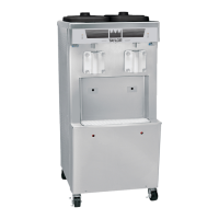
Model 358 Operator Parts 31............................................
Model 358 Exploded View 32............................................
Model 358 Shell Assembly 34...........................................
Model 358 Control A. (X66731-33) 35....................................
Model 358 Channel A.-Control (X63534) 36...............................
Models 358 & 359 Beater Door Assembly 38..............................
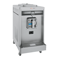
Model 359 Operator Parts 39............................................
Model 359 Exploded View 40............................................
Model 359 Shell Assembly 42...........................................
Model 359 Channel A.-Control (X65222) 43...............................
Model 359 Control A. (X65279-33) 44....................................
Models 358 & 359 Switch A.-Draw (X65212-SER) 45.......................
Models 358 & 359 Accessories 46.......................................
Parts List 47...........................................................
Wiring Diagrams 54....................................................
CAUTION: Information in this manual is intended to be used by Taylor Authorized
Service Technicians only.
Note: Continuing research results in steady improvements; therefore, information
in this manual is subject to change without notice.
E August, 2010 Taylor (Original Publication)
(Updated March, 2011)
All rights reserved.
056788-S
The word Taylor and the Crown design
are registered trademarks in the United States
of America and certain other countries.
Taylor Company
750 N. Blackhawk Blvd.
Rockton, IL 61072
 Loading...