16
Operating Procedures
Models 702/741/772
Note: To prevent costly damage, the hole in the
scraper blade must fit securely over the pin.
If the blades are in good condition, place the rear
scraper blade over the rear holding pin on the beater,
knife edge to the outside. Holding the rear blade on the
beater, slide the assembly halfway into the freezing
cylinder. Install the front scraper blade over the front
holding pin. Slide the beater assembly the rest of the
way into the freezing cylinder.
Figure 8
Make sure the beater assembly is in position over the
drive shaft. Turn the beater slightly to be certain that
the beater is properly seated. When in position, the
beater will not protrude beyond the front of the freezing
cylinder.
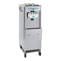
Step 3
Install the draw valve. Slide the two o-rings into the
grooves on the draw valve and lubricate them with
Taylor Lube.
Figure 9
Lubricate the inside of the freezer door spout, top and
bottom. Insert the draw valve into the freezer door from
the top . It will be necessary to rotate the draw valve to
the right when assembling the door to the freezer .
Figure 10
Step 4
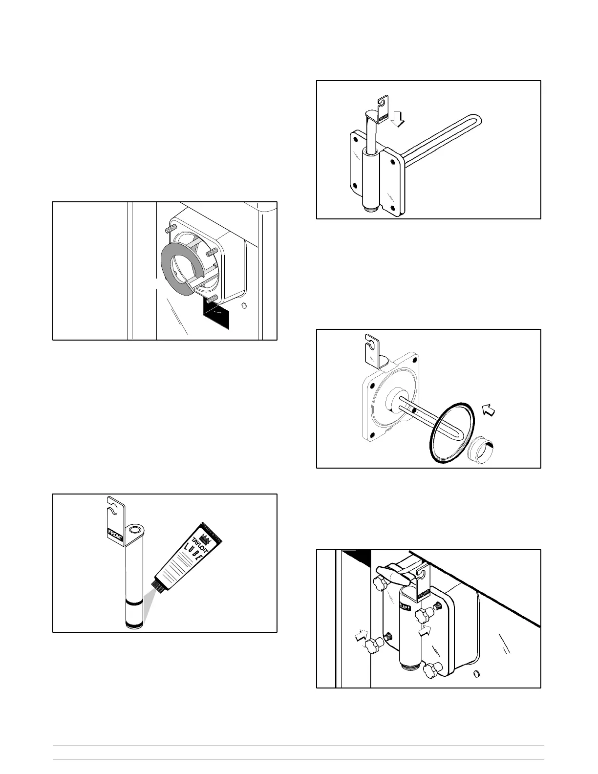
Install the freezer door. Place the freezer door gasket
into the groove on the back of the freezer door. Slide
the front bearing over the baffle rod so the flanged
edge is against the door. Do not lubricate the gasket
or bearing.
Figure 11
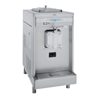
Insert the baffle rod through the beater in the freezing
cylinder. With the door seated on the freezer studs,
install the handscrews. Tighten equally in a crisscross
pattern to insure that the door is snug.
Figure 12