Do you have a question about the Taylor C709 and is the answer not in the manual?
Safety precautions for machine installation, including PPE and electrical safety.
Guidelines for choosing and preparing the installation site for the machine.
Electrical connection requirements and safety measures for installation.
Information and warnings regarding refrigerant handling and environmental impact.
Introduction to operating the machine and its benefits for product quality.
Emphasizes reading the manual and details warranty validity conditions.
Compliance statements for FCC and Industry Canada regarding radio frequency.
Essential safety warnings and guidelines for machine operation and maintenance.
Safety measures related to electrical connections, grounding, and power supply.
Warnings about operating the machine with panels removed or moving parts exposed.
Precautions regarding hot product, sharp blades, and cleaning procedures.
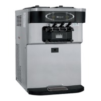
Identifies parts for Model C709 using an exploded view diagram.
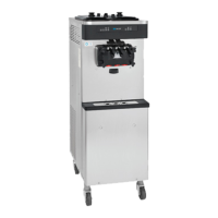
Identifies parts for Model C717 using an exploded view diagram.
Lists parts for the feed tube assembly, accessories, and cleaning brushes.
Identifies the main components of the user interface control panel.
Explains symbols, indicator lights, power switch, and display functions.
Explains standby feature, reset mechanism, and draw handle adjustment.
Feed tube operation, screen descriptions, and power-up initialization checks.
Details Heat cycle status, power status, and lockout conditions.
How to access and navigate the Manager's Menu using access codes.
Lists menu options like Servings Counter, Set Clock, and time configurations.
Describes faults, history logs, system information, and current conditions.
Step-by-step guide for assembling the freezing cylinder and freezer door.
Procedures for sanitizing and priming the machine before operation.
Steps for daily opening, closing, manual cleaning, and disassembly.
Checkpoints for cleaning, sanitizing, and regular maintenance operations.
Procedures for protecting the machine during winter or long closures.
Troubleshooting for lockouts, no product, or incorrect product consistency.
Troubleshooting for hopper temperature, probes, and control panel faults.
Troubleshooting for mix leakage, driveshaft problems, and cylinder scoring.
Table indicating parts replacement frequency (3, 6, 12 months).
Details warranty periods, conditions, and exclusions for equipment.
Details warranty periods and exceptions for genuine Taylor parts.