Do you have a question about the Taylor C707 and is the answer not in the manual?
Steps for preparing the installation area.
Critical safety precautions for installation personnel.
Installation requirements for airflow and indoor use.
Instructions for connecting water supply to water-cooled units.
Guidelines for safe and compliant electrical hookup.
Details about refrigerant and handling precautions.
Procedure for setting beater motor rotation direction.
Advice on operating for consistent product quality.
Information on compressor warranty and refrigerant use.
Crucial safety warnings for operating the equipment.
Warnings and procedures related to electrical hazards.
Safety guidelines for using the machine and handling parts.
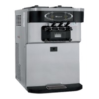
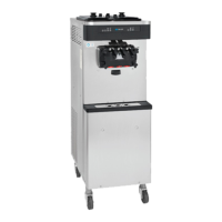
Identification of major components for the Model C707.
Detailed parts breakdown of the door and beater assembly.
Identification of various brushes used for cleaning.
Explanation of the control panel layout and indicators.
Explanation of international symbols used on controls.
Details on MIX REF, STANDBY, WASH, and AUTO keys.
Procedure for resetting the beater motor overload.
How to adjust the draw handle for portion control.
Explanation of the feed tube's function and installation.
Step-by-step guide for assembling the freezer components.
Procedure for cleaning and sanitizing the unit and its parts.
Instructions for priming the freezer with fresh mix.
Steps for closing the unit after operation.
Procedures for draining product, rinsing, and cleaning the unit.
Steps for disassembling and cleaning parts with brushes.
Checklist items for proper cleaning and sanitizing.
Steps to address issues related to bacterial counts.
Schedule and procedures for routine maintenance.
Precautions for storing the unit during winter.
Table listing issues, causes, and remedies.
Chart detailing parts replacement frequency.
Details on equipment warranty coverage and limitations.
Information on warranty periods for genuine Taylor parts.
Comprehensive list of parts with numbers.
Diagrams illustrating the unit's electrical connections.
| Power | 208-230V, 60Hz, 1Ph |
|---|---|
| Minimum Clearance | 6" on both sides |
| Water Inlet | 3/8" FPT (Water Cooled) |
| Water Outlet | 3/8" FPT (Water Cooled) |
| Separate Hopper Refrigeration | Maintains mix below 41ºF (5ºC) during Auto and Standby modes. |