TBS Installation Manual – 2D IRON & 3D AIR
TBS 2D IRON 3D AIR Mounting and Installation Guideline • TBS-056-057 • Rev 09-2023 page 16 of 21
Serial Interface RS485
Please connect from TBS device RS485 port directly to controller:
For farthest terminal, a 120-Ohm resistor termination may be added outside the terminal between D+
and D-.
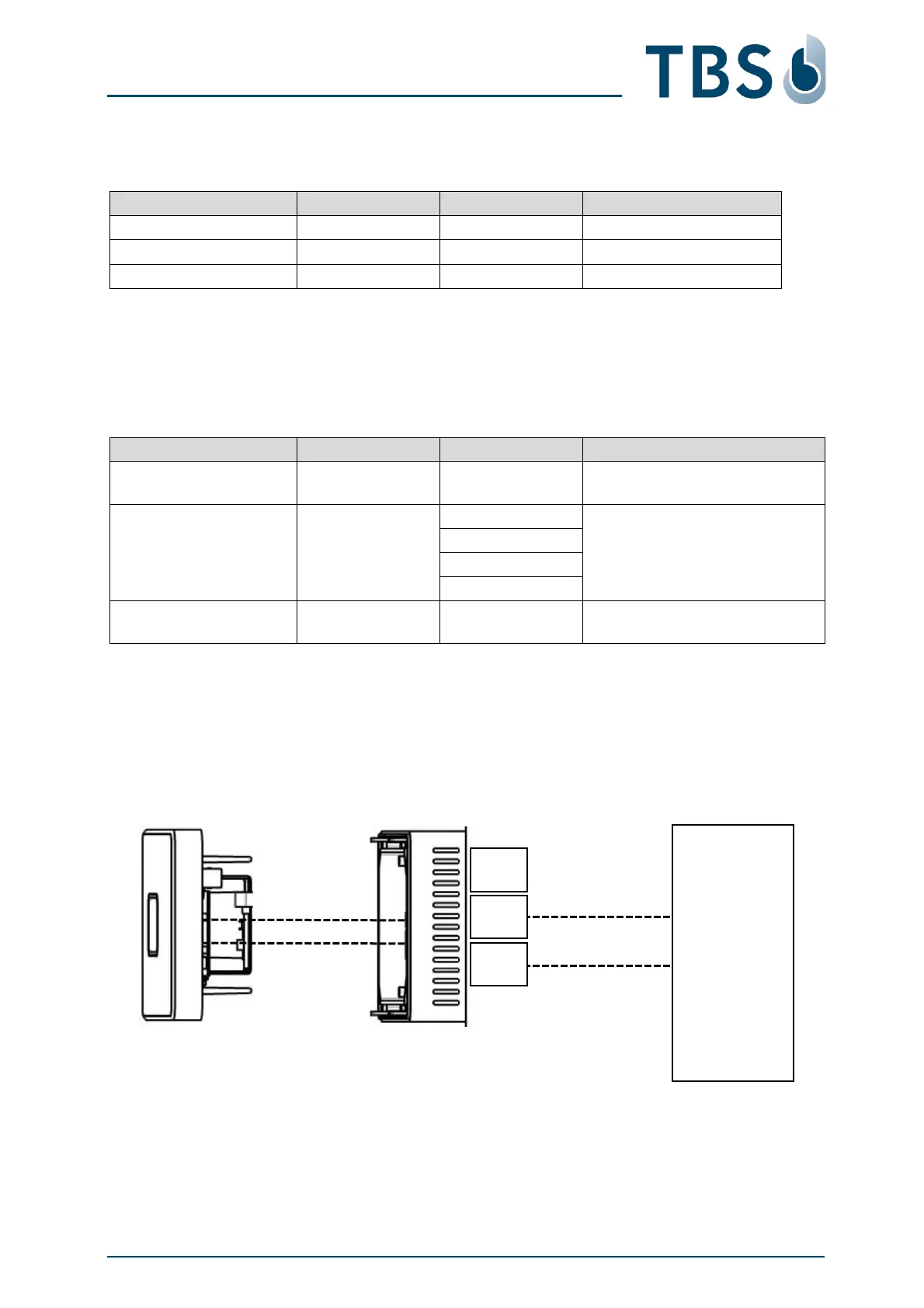
5.8 Tamper Switch
The tamper switch is activated when the front panel is separated from the back panel. When the tamper
switch is activated, it closes like a relay.
A recommended way of utilizing the tamper switch is shown in the image below. As long as the front
and back panels are connected, the tamper switch relay connects C (common) to NO (normally open).
An alarm device is connected to a power line (e.g. 5 V DC) going through the tamper switch. As long
as it senses the power, no tampering has been taken place. Should the front panel be removed, the
tamper switch closes, and the 12 V line is broken, thus engaging the alarm. With this setup, the alarm is
also engaged when the terminal is cut from power entirely.
External
Alarm Sensing
Device
TBS Terminal Back