KMS-2/Exia Transmitter
Installation and Operating Manual
ATEX
Rev D 20/09/2018 KMS-2/Exia IOM Page 7 of 13
Electrical Connections
Unscrew the lid to gain access to the rear terminal enclosure; the terminal block can then be removed to
facilitate connections.
Select the correct cable entry point dependent on the orientation of the sensor. The connection cable should
be bought in through an M20 gland suitable to maintain the required IP rating, and then connected to the +
and – terminals.
To prevent the risk of moisture ingress ensures that the connection cable is led downward in front of the
cable gland
Cable Selection
The connection cable should be a twisted pair type suitable for the expected ambient conditions.
When a screened cable is used, the screen should be connected to the internal earth connection provided.
Hazardous area Installation
The installation of this unit must be in compliance with the applicable national
requirements
i.e. EN60079-14.
Intrinsically Safe Circuits
The connection cable shall be identified to prevent confusion with non-intrinsically safe circuits where a
colour code is used it should be light blue.
The total inductance and capacitance of the cable shall not exceed the values stated on the intrinsically safe
control device for the required gas group.
The connection cable should be bought in through the M20 cable entry via a suitable gland as necessary to
maintain the required IP rating (minimum IP54).
When refitting the lid ensure that the sealing gasket is correctly fitted into the lid recess.
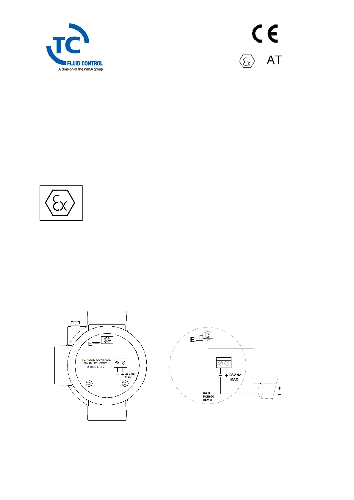
Fig 3 Cable entry via M20 Gland Fig 4 Connection Details
28V dc
MAX
K&TC
PCB620
REV D
+
E
+