6. STEERING SYSTEM
- 91 -
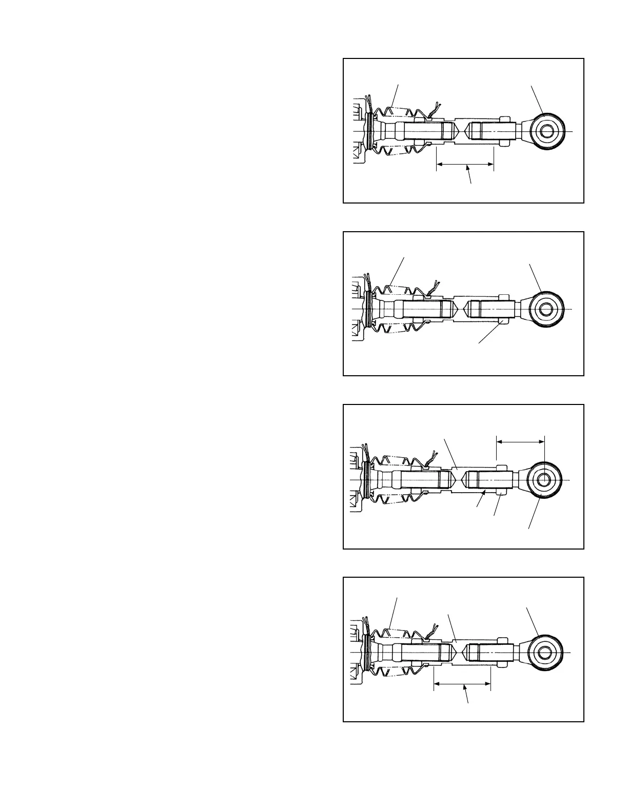
Fig. 6.15
Fig. 6.16
Fig. 6.17
Fig. 6.18
(2) Replacing the ball joint
①
Securely x the ball joint with its connector held
in a vise.
②
Loosen the lock nut of the ball joint, then
remove the ball joint.
③
Apply LOCTITE#271 to the threaded areas of
the connector and lock nut. Then install the ball
joint.
(3) Replacing the boot
①
Hold the connector section in a vise.
Hold this section by vise
LOCK NUT
BALL JOINT
Hold this section.
•
•
•
•
•
•
•
•
BOOT
BALL JOINT
BOOT
BALL JOINT
CONNECTOR
61 ± 2 mm
[2.4 ± 0.078 in.]
Apply LOCTITE#271
LOCK NUT
BOOT
CONNECTOR
BALL JOINT
 Loading...
